Transformer Dry Air Generator Dew Point Selection: -40°C vs -70°C

Power Utility Gas & Insulation Specialist
Table of Contents
During the installation, overhaul, and internal inspection of high-voltage power transformers, preventing moisture ingress into the internal insulation system is a primary technical requirement. Transformer solid insulation consists of cellulose-based pressboard and paper, which possess high hygroscopicity. When the transformer core and windings are exposed to ambient air during maintenance, the insulation paper rapidly absorbs ambient moisture. This process increases the moisture content of the insulation, which subsequently degrades the dielectric strength of the transformer oil and accelerates the thermal aging rate of the cellulose structure.
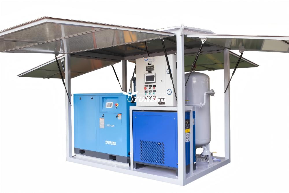
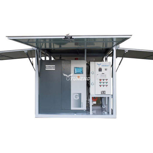
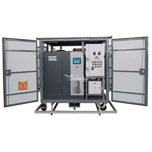
To reduce this risk, a dry air generator is used to provide a constant flow of low dew point, high-purity air into the transformer tank to maintain a positive pressure at all times to prevent the ingress of ambient humid air. The output dew point parameter is normally set between −40 ℃ and −70 ℃. The choice of this parameter is a critical variable in the engineering specifications, which directly affects the safety margin of the insulation and the operational cost of the equipment.
The Physical Relationship Between Dew Point and Atmospheric Moisture Content
The term “dew point” defines the specific temperature to which air must be cooled, at constant barometric pressure, for water vapor to condense into liquid water. In industrial applications involving a dry air generator, the dew point serves as a direct metric for measuring the absolute moisture volume fraction within the output gas stream, usually quantified in parts per million (ppm) by volume.
Moisture Volume Fraction (ppm)∝f(Dew Point Temperature)
The residual water vapor content in the air stream is about 120 ppm when the dry air generator is operating at an output dew point of −40 ℃. Increasing the performance parameters of the dry air generator to achieve an output dew point of −70 ℃ reduces the residual water vapor concentration to approximately 11 ppm. This represents a tenfold reduction in absolute water molecule density within the injected air stream.
The underlying mechanism of moisture transfer between the transformer insulation paper and the surrounding air is governed by the equilibrium vapor pressure differential. If the vapor pressure of the air delivered by the dry air generator is higher than the equilibrium vapor pressure of the insulation paper, water molecules migrate from the gas phase into the solid cellulose matrix. Consequently, maintaining a lower dew point reduces the vapor pressure of the gas phase, minimizing or eliminating the rate of moisture absorption by the transformer core components during atmospheric exposure.
Technical Comparison: -40°C vs. –70°C Output Parameters
To achieve different dew point thresholds, the internal process configurations of the dry air generator must be altered, which leads to varying operational requirements, energy expenditures, and maintenance schedules.
| Technical Parameter / Metric | -40°C Dew Point Configuration | –70°C Dew Point Configuration |
| Residual Moisture Content (Volume) | ≈120 ppm | ≈11 ppm |
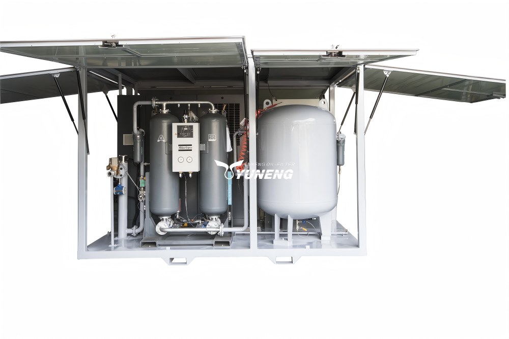
| Drying Method Architecture | Single-stage desiccant adsorption or combined refrigeration-adsorption system. | Multi-stage high-efficiency dual-tower adsorption system. |
| Desiccant Media Requirements | Standard activated alumina or synthetic zeolite matrix. | High-grade synthetic molecular sieve combination (e.g., 3A/4A/13X optimization). |
| Regeneration Gas Consumption Rate | 5%∼10% of total processed air volume. | 12%∼20% of total processed air volume. |
| Thermal Regeneration Energy Demand | Baseline thermal input (140∘C∼180∘C heating elements). | 35%∼50% higher thermal input (180∘C∼240∘C heating elements). |
| Equipment Capital Expenditure (CAPEX) | Standard base valuation. | Approximately 40%∼70% higher than standard valuation. |
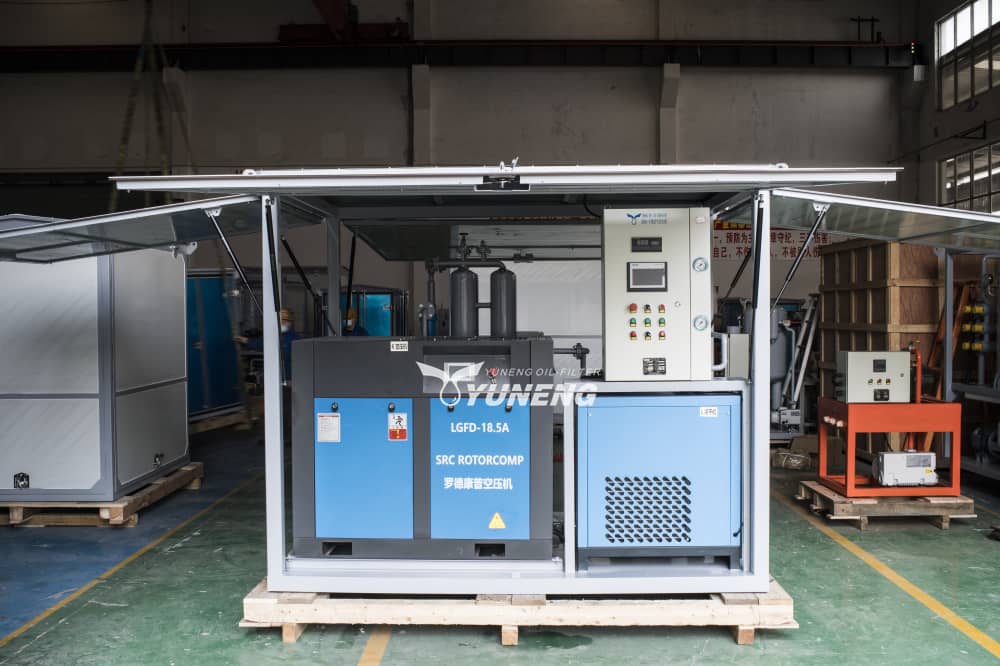
Process Engineering of the Dry Air Generator
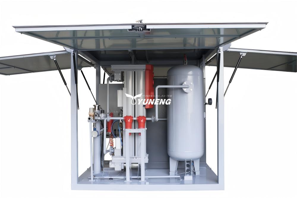
A standard dry air generator configured for a −40 ℃ dew point typically uses a combined system where a refrigerated dryer removes bulk water, followed by an adsorption dryer twin-tower setup.
To achieve a stable −70 ℃ dew point, the dry air generator must utilize specialized synthetic molecular sieves with uniform pore structures optimized for water molecule trapping. The regeneration phase for a −70 ℃ dry air generator requires higher thermal energy inputs to completely break the dipole bonds between the water molecules and the crystalline framework of the adsorbent media. This demands robust heating elements and shorter cycle switching intervals, increasing mechanical wear on the internal switching valves and pneumatic actuators.
Engineering Selection Criteria of Dry Air Generator for Transformer Maintenance
The selection of the dew point parameter for a dry air generator is determined by three variables: transformer voltage rating, ambient relative humidity during execution, and the duration of core exposure.
Voltage Rating Specifications
- ≤110 kV Transformers: The structural design margins for electric field stress in these units can accommodate minor variations in insulation moisture content. A dry air generator delivering a −40 ℃ dew point provides an adequate safety threshold under standard conditions.
- 220 kV∼750 kV Transformers: The operating electric field stress within the oil-paper insulation matrix is high. Any local accumulation of moisture can lower the critical partial discharge inception voltage (PDIV). For these voltage tiers, standard engineering protocols specify the use of a dry air generator operating at a minimum of −70 ℃ dew point.
- ≥1000 kV UHV (Ultra-High Voltage) Units: These systems require a stable −65 ℃ or lower output parameter from the dry air generator to ensure zero moisture transfer during the entire installation process.
Ambient Environmental Constraints
The relative humidity (RH) of the external environment modifies the selection matrix. If maintenance occurs in environments where the ambient relative humidity exceeds 80% (such as coastal areas or during high-precipitation seasons), a dry air generator running at −40 ℃ may fail to maintain the necessary low moisture gradient inside the tank due to micro-leakages at the flange seals or manhole covers. Under high-humidity ambient parameters, a −70 ℃ dry air generator must be deployed regardless of the transformer’s voltage rating to counteract ambient humidity infiltration.
Operational Requirements for Maintaining Stable Low Dew Point Output
Deploying a high-performance dry air generator requires strict adherence to operational variables to prevent dew point degradation during field execution.
Control of Inlet Air Temperature and Oil Contamination
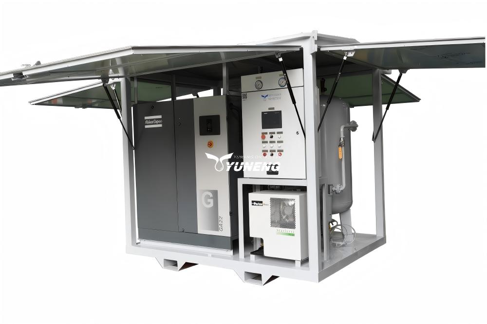
The adsorption efficiency of the desiccant media inside the dry air generator is inversely proportional to the temperature of the incoming compressed air. If the air entering the adsorption towers exceeds 40 ℃, the equilibrium capacity of the molecular sieve decreases, causing the output dew point to rise above the −70 ℃ specification.
Furthermore, if oil vapor from the air compressor bypasses the primary filtration stages and reaches the desiccant beds, it coats the micro-pores of the molecular sieve. This creates a permanent structural barrier called desiccant poisoning. To prevent this, multi-stage coalescing filters and activated carbon towers must be integrated upstream of the drying process within the dry air generator assembly.
Piping Material Parameters and Diffusion Control
A common point of operational failure occurs when a dry air generator registers a correct −70 ℃ dew point at its exit manifold, but the dew point measured at the entry point of the transformer tank drops to −35 ℃. This discrepancy is caused by water vapor counter-diffusion through the walls of the delivery piping.
In traditional industrial rubber hoses, the atmospheric water vapor could diffuse through the polymer matrix to the dry air stream. Systems that require a low dew point dry air generator must employ non-porous delivery lines such as corrugated stainless steel hoses or rigid polytetrafluoroethylene (PTFE) conduits to maintain gas purity over long transfer distances.
Frequently Asked Questions (FAQ)
Q1: Does a lower dew point setting on a dry air generator always yield superior results for all transformer types?
A1: From a technical insulation standpoint, lower moisture levels are always safer. However, from an operational economy perspective, configuring a dry air generator to maintain a −70 ℃ dew point on low-voltage assets (35 kV or below) introduces unnecessary financial costs. The higher power consumption, increased regeneration purge air loss, and accelerated wear on switching components do not provide justifiable returns for equipment with wider insulation design tolerances.
Q2: What causes a sudden rise in the output dew point of an active dry air generator during field operation?
A2: A rapid increase in output dew point is typically traceable to three faults: a mechanical failure of the pneumatic switching valves causing both towers to partially open simultaneously, a malfunction in the heating elements of the regeneration tower preventing the complete desorbing of moisture, or liquid water carryover overloading the pre-filters due to a failed automatic drain valve on the compressor’s aftercooler.
Q3: How can an operator verify the accuracy of the dew point reading on a dry air generator?
A3: The integration of an online, calibrated polymer capacitive or chilled-mirror dew point transmitter at the main output manifold is required. Field cross-verification must be executed using a portable, calibrated dew point meter attached to a dedicated sampling port. Measurements must be taken only after the sampling line has been purged with dry air for at least 15 minutes to eliminate ambient moisture remnants from the testing apparatus.