Transformer Oil Dissolved Gas Analysis: 7 Fault Gases and Solutions

Oil Purification & Vacuum Technology Expert
Table of Contents
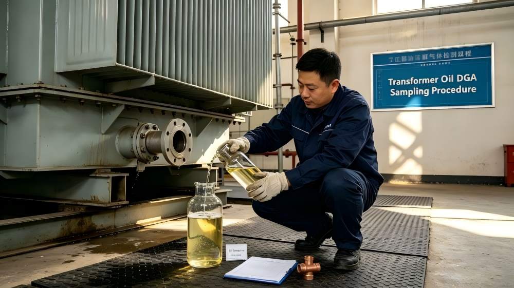
Dissolved gas analysis of transformer oil is the most critical diagnostic technique for identifying internal incipient faults in electrical power transformers. Liquid insulation, typically mineral-based transformer oil, and solid insulation material, composed of cellulose paper, undergo chemical degradation under mechanical, thermal, and electrical stresses. This degradation process breaks down the hydrocarbon bonds of the oil and the carbohydrate chains of the cellulose, releasing specific gaseous byproducts that dissolve into the oil. By monitoring the concentration, generation rate, and ratios of these fault gases, asset managers can detect internal anomalies—such as severe overheating, partial discharge, and high-energy arcing—long before a catastrophic insulation breakdown occurs. Failing to detect these gases accurately leads to unplanned outages, massive capital losses, and catastrophic equipment failure.
Transformer Oil Dissolved Gases and Fault Types
The following structured matrix outlines the seven key diagnostic gases monitored during standard diagnostic procedures, mapping each gaseous byproduct to its primary fault indication, general temperature generation threshold, and the energy classification of the anomaly.
| Gas Formula | Gas Name | Primary Fault Indication | Critical Operational Temperature Range |
| H2 | Hydrogen | Partial Discharge (PD) / Corona | Low Energy / Low Temperature Electrical Stress |
| C2H2 | Acetylene | High-Energy Arcing / Short Circuit | High Energy / Thermal Flashpoints Exceeding 700℃ |
| CO | Carbon Monoxide | Cellulose Insulation Overheating | Thermal Decomposition of Solid Paper (150℃−300℃) |
| CO2 | Carbon Dioxide | Severe Solid Insulation Degradation | High-Temperature Cellulose Degradation (>300℃) |
| CH4 | Methane | Low-Temperature Thermal Fault | Liquid Hydrocarbon Decomposition (<300℃) |
| C2H6 | Ethane | Medium-Temperature Thermal Fault | Liquid Hydrocarbon Decomposition (300℃−500℃) |
| C2H4 | Ethylene | High-Temperature Thermal Fault | Severe Overheating of Oil / Core (>500℃) |
Chemical and Diagnostic Breakdown of the 7 Key Transformer Oil Dissolved Gases
Mineral oil is chemically stable due to its hydrocarbon structures (paraffinic, naphthenic and aromatic bonds). – Localised energy from an internal fault cleaves specific chemical bonds based on their various bond dissociation energies. The specific gases that reform from these free radicals provide a fingerprint of the internal core conditions.
1. Hydrogen (H2) – Partial Discharge
Hydrogen in transformer oil is the predominant indicator of partial discharge (PD), low-level ionic ionisation, and localised corona activity. The chemical mechanism is based on low-energy electrical stresses that cleave the weakest carbon-hydrogen (C-H) bonds. Hydrogen gas atoms are easily removed from hydrocarbon chains under ionic bombardment since the energy thresholds for breaking CH bonds are lower than those for CC bonds. The constant evolution of H2 suggests localised dielectric tracking or gas bubbles trapped in the oil channels or weak spots in the insulation due to moisture. While categorized as a low-energy fault byproduct, high H2 generation rates accelerate oil oxidation and lower the impulse breakdown voltage of the surrounding fluid.
2. Acetylene (C2H2 ) – High-Energy Arcing
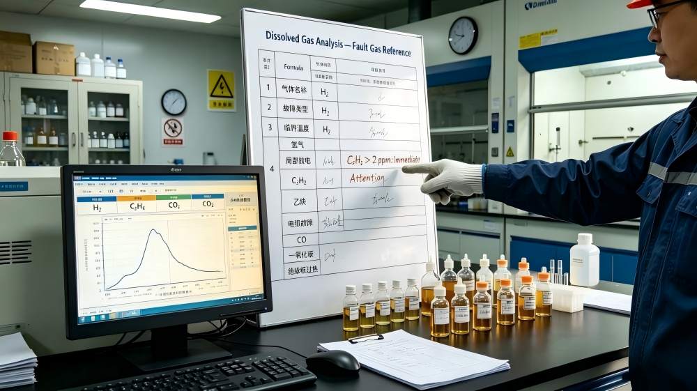
Acetylene in transformer oil is the most critical diagnostic indicator of high-energy arcing, severe electrical short circuits, or continuous heavy sparking. The formation of C2H2 is highly localised at a thermal threshold of >700℃ to 800℃. Under these extreme conditions, the liquid hydrocarbons fall apart into highly unstable carbon radicals, which recombine to triple-bonded acetylene molecules. Physical faults leading to this are usually winding-to-winding flashovers, selection switch failures in the on-load tap changer (OLTC), or disconnection of the grounding wire. Acetylene generation is never normal in the main transformer tank. Even minor increases, such as concentrations exceeding 1 to 2 ppm, necessitate immediate diagnostic investigation, operational load reduction, or offline diagnostic testing to prevent tank explosions.
3. Carbon Monoxide (CO) – Cellulose Aging
Carbon Monoxide (CO) in transformer oil signifies the thermal decomposition and fundamental chemical degradation of solid cellulose paper insulation. Unlike the liquid mineral oil, the solid structural insulation is composed of polymer chains of glucose units linked by glycosidic bonds. When the winding conductors run hot due to continuous overloads or restricted cooling ducts, temperatures between 150 ℃ and 300 ℃ trigger the thermal cleavage of these carbon-oxygen-hydrogen structures. Monitoring CO tracking is essential because while old transformer oil can be reconditioned, degraded paper insulation loses its structural tensile strength permanently, rendering the transformer vulnerable to physical collapse under short-circuit mechanical forces.
4. Carbon Dioxide (CO2) – Severe Paper Degradation
Carbon Dioxide (CO2) in transformer oil indicates extensive, widespread cellulose insulation degradation or extreme operational overheating conditions exceeding 300 ℃. While baseline levels of CO2 accrue naturally due to atmospheric ingress and ambient chemical oxidation in open-breather transformers, sudden spikes signal severe structural paper degradation. Diagnostic engineers evaluate the CO2/CO ratio rather than analyzing absolute values in isolation. A healthy transformer maintains a ratio between 3 and 11. When this ratio drops below 3, it confirms an active, localized high-temperature fault directly attacking the structural paper insulation wrapping the conductive copper coils.
5. Methane (CH4) – Low-Temperature Thermal Fault
Methane (CH4) denotes low-temperature thermal faults within the liquid insulation body at ranges below 300 ℃. When a localized component—such as an uninsulated structural bolt, a magnetic shield plate, or a core lamination stack—experiences stray eddy currents, it generates mild hot spots. This level of thermal stress provides enough kinetic energy to break aliphatic C−H bonds, yielding free methyl radicals (⋅CH 3). These radicals quickly capture available hydrogen atoms to synthesize stable methane gas. This represents an early-stage warning indicator of poor oil circulation or localized core clamping degradation.
6. Ethane (C2H6) – Medium-Temperature Thermal Fault
Ethane (C2H6) indicates medium temperature thermal faults typically from 300°C to 500°C. This range of temperature is in agreement with the thermal energy needed to break the single C-C bonds in the paraffinic structures of the fluid. Ethane build-up indicates growing structural thermal anomalies, which include failing contact points on the internal terminal blocks, high resistance joints on lead connections, or localised core-clamping structure failures. The existence of ethane is a sign of a developing minor thermal hot spot, which should be subject to regular oil sample analysis.
7. Ethylene (C2H4) – High-Temperature Thermal Fault
Ethylene (C2H4) serves as the primary operational indicator for high-temperature thermal faults operating above 500 ℃. The formation of double-bonded ethylene requires substantial energy to initiate the rapid cracking of long-chain naphthenic and paraffinic hydrocarbons. Common physical causes include severe magnetic core multi-point grounding faults, large circulating currents in the transformer structural frame, or loose, heavily oxidized internal busbar connections. High ethylene levels indicate an unstable thermal environment that will rapidly accelerate the destruction of adjacent solid insulation materials if left unmanaged.
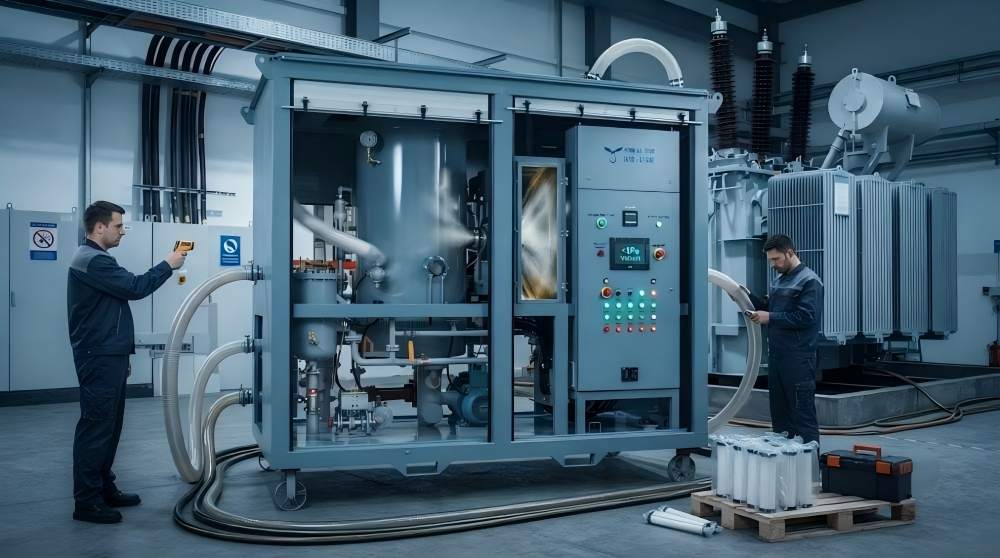
How to Remove Dissolved Gases: Transformer Oil Purification Machine
When dissolved gas analysis confirms that combustible gas concentrations exceed safety limits defined by international standards such as IEEE C57.104 or IEC 60599, corrective filtration actions must be executed. High concentrations of dissolved combustible gases reduce the oil’s fluid flashpoint, compromise its dielectric insulation properties, and risk triggering pressure relief devices.
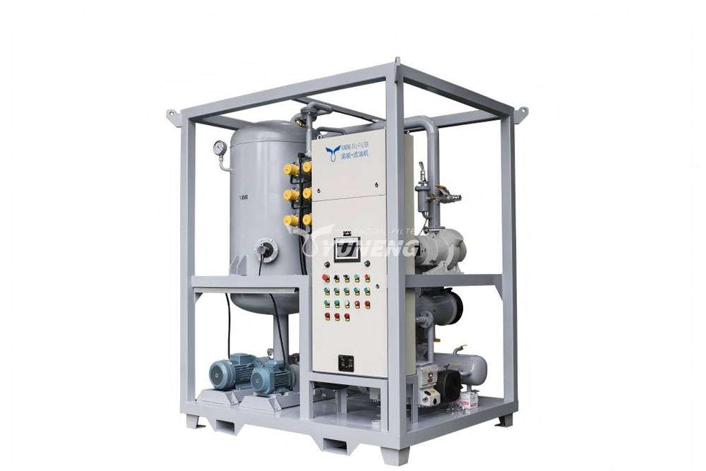
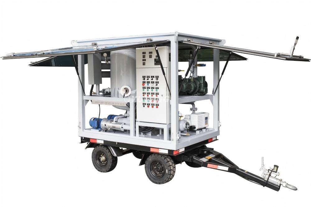
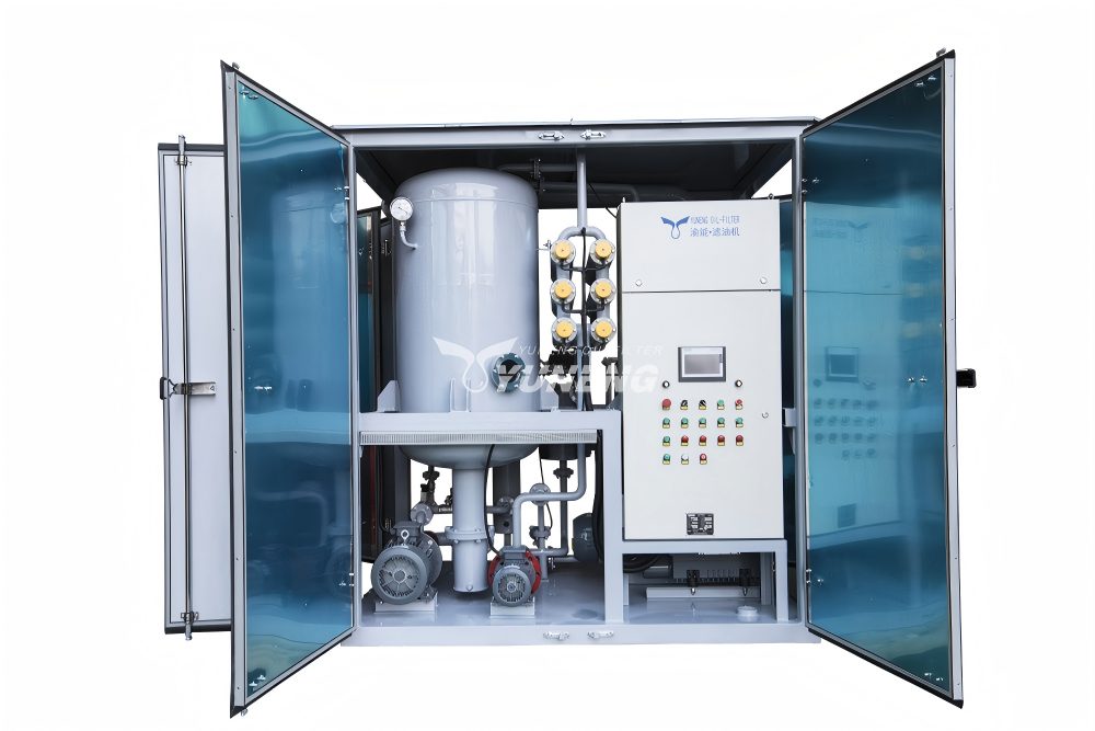
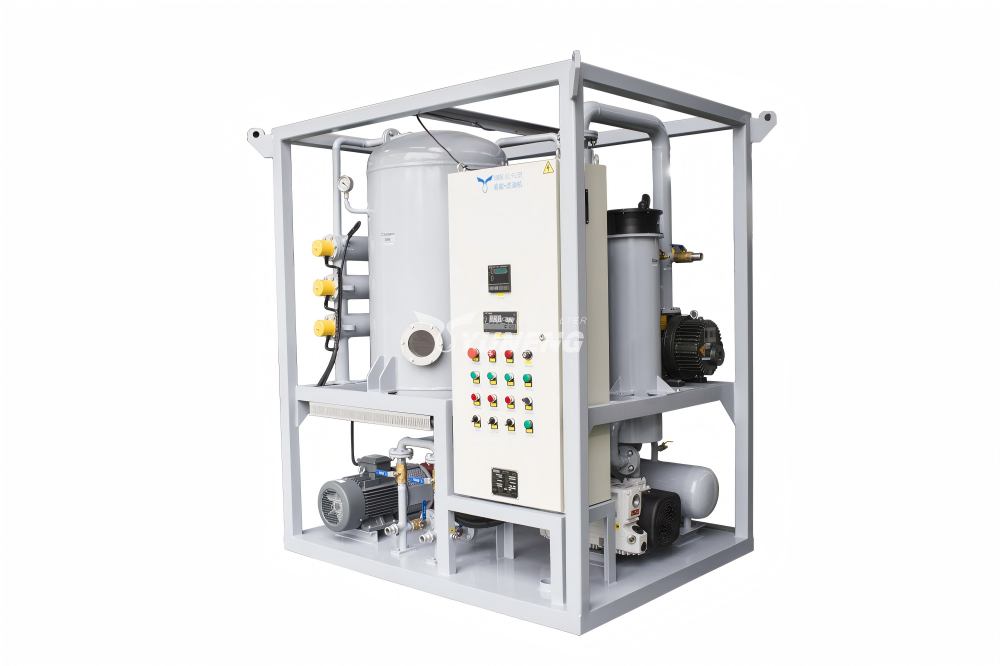
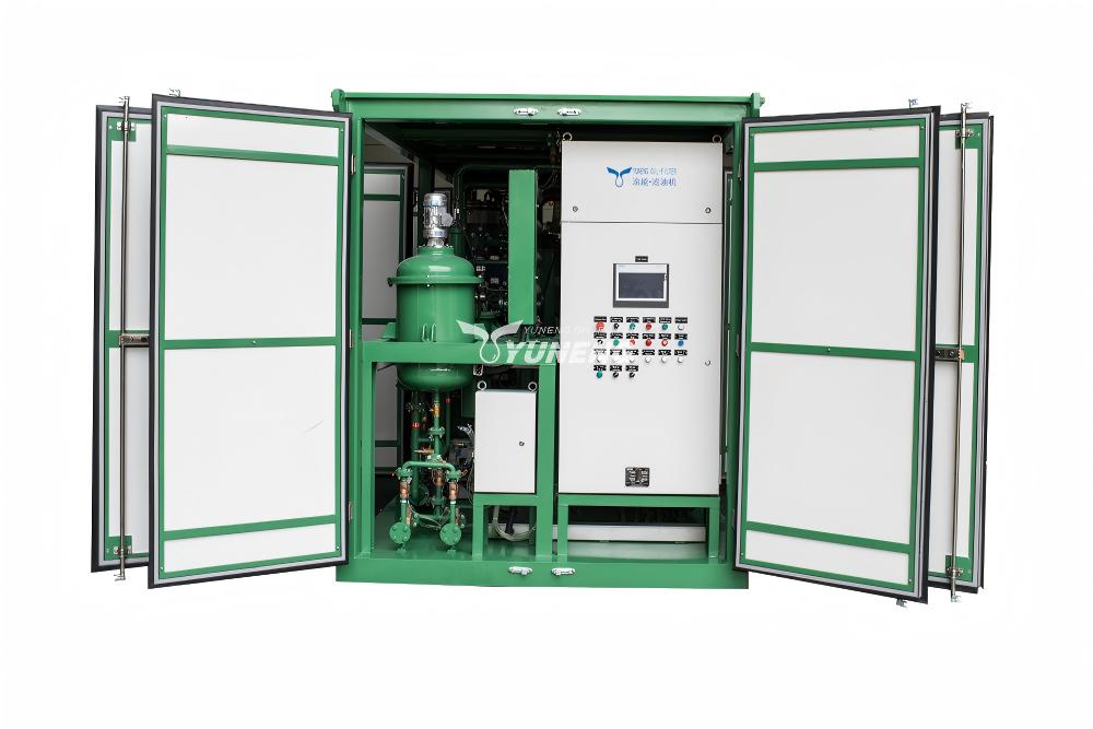
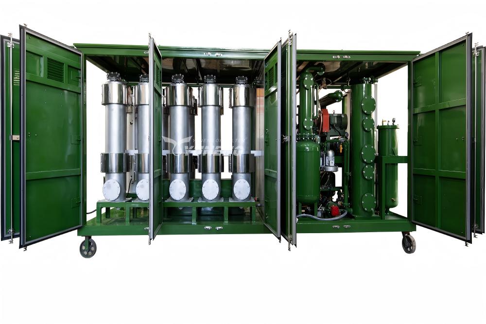
To extract these volatile fault gases and moisture, field operations utilize an industrial-grade transformer oil purification system. This specialized processing layout treats the oil under vacuum to restore the chemical and electrical parameters of the dielectric fluid.
The extraction process relies on an industrial transformer oil purification machine configured with a double-stage high-vacuum engineering array:
- Double-Stage High-Vacuum Architecture: The extraction plant uses a primary mechanical backing pump integrated with a secondary Roots booster pump. This dual configuration lowers the internal pressure of the process tank down to ≤5 Pa, with an ultimate working vacuum threshold reaching ≤10 Pa. Under this deep vacuum, the partial pressure of dissolved gases drops, forcing them out of solution.
- Three-Dimensional Flash Evaporation Technology: The system passes incoming oil through atomization nozzles or slotted vertical plates inside the vacuum chamber to maximize surface area. This thin-film separation process speeds up the removal of dissolved water and low-boiling-point gases (H2, C2H2, CH4 ) from the fluid matrix.
- Micro-Particle Contaminant Filtration: The process includes multi-stage micro-glass filters to capture solid carbon tracking, metallic particles, and paper fibers down to an absolute rating of 1 μm. Removing these conductive particles, alongside vacuum degassing, restores the transformer oil’s dielectric breakdown voltage to ≥70 kV.
Frequently Asked Questions about DGA
Q1: Which individual gas indicates the most severe internal transformer risk?
A1: Acetylene (C2H2) represents the highest operational risk. Its presence confirms active high-energy arcing or a direct short-circuit fault inside the tank, conditions that can cause rapid gas pressure buildup and catastrophic equipment explosion.
Q2: Why does cellulose aging produce carbon-based oxides instead of pure hydrocarbons?
A2: Cellulose paper is essentially made from complex oxygenated carbohydrate polymers. Mineral oil is made up of only hydrogen and carbon structures. The oxygen-hydrogen and carbon-oxygen functional groups present decompose into CO and CO2 under localised thermal stress.
Q3: What distinguishes a basic oil filter from a double-stage transformer oil purification system?
A3: A basic filter unit only removes solid particles and surface moisture using mechanical particulate filters. A double-stage vacuum purification machine utilizes deep vacuum technology (≤5 Pa) and thermal conditioning to extract chemically dissolved gases and bound moisture at the molecular level, restoring the oil’s dielectric strength.