Transformer Oil Purification Guide: Process, Equipment, Testing & Best Practices

Oil Purification & Vacuum Technology Expert
Table of Contents
Electrical power transformers are the backbone of modern energy infrastructure, responsible for stepping voltage levels up and down throughout transmission and distribution networks across the globe. High operational efficiency and the prevention of catastrophic grid failures are dependent on the use of specialized liquid insulation in power transformers. The most important preventative maintenance method applied to transformer dielectric fluids is transformer oil purification to remove moisture, dissolved gases, particulate contamination, and acidic sludge. Without precise and continuous transformer oil maintenance, solid cellulosic insulation deteriorates rapidly, causing flashover faults, unplanned downtime, and multi-million dollar replacement costs.
What Is Transformer Oil Purification?
Basic structural elements of the modern power transmission and distribution infrastructure are the electrical transformers. The insulating oil, usually mineral oil, synthetic ester, or natural ester, in liquid-filled power and distribution transformers acts as the dielectric medium of high voltage and the dynamic cooling medium. Operational thermal stress, electrical discharge, ambient oxygen exposure and atmospheric moisture ingress degrade the oil’s physical, chemical and dielectric integrity over prolonged operational lifecycles.
Transformer oil purification is a specific engineering process of systematic removal of moisture (free, emulsified and dissolved), dissolved combustible and non-combustible gases, suspended solid particulate matter, sludge, oxidation byproducts and polar organic contaminants from transformer insulating oil. The main aim is to recover the dielectric breakdown voltage (BDV), heat transfer capacity, and the physical properties of the oil up to the level conforming to the stringent operational standards of IEEE and IEC, international standards.
Core Functional Duties of Insulating Oil
- Dielectric Insulation Function: Maintains high breakdown strength to prevent electrical flashovers, phase-to-ground arcing, and internal partial discharges across high-voltage windings and core components.
- Thermal Cooling Function: Absorbs the heat produced by core hysteresis and copper/aluminum winding electrical losses (I2R losses) and dissipates it by convective circulation through external radiator banks.
- Chemical & Oxidation Protection: Protects internal solid cellulose (paper and pressboard) insulation structures from atmospheric oxygen ingress, minimizing cellulose chain degradation and structural mechanical embrittlement.
[TECHNICAL NOTE] Purification of transformer oil is not only mechanical filtration. Purification involves multi-stage micro-filtration coupled with high-vacuum thermal degassing and dehydration, which efficiently removes dissolved gases and molecularly bound water from the fluid.
Why Transformer Oil Needs Purification
Operating power transformers are high-value capital assets subject to continuous thermal, mechanical, and electrical stresses. Allowing contaminated oil to circulate through a transformer triggers accelerated aging mechanisms that catastrophically diminish the asset’s operational lifespan.
Mechanisms of Oil Degradation
Moisture Contamination: Water is the single greatest enemy of liquid-filled electrical insulation. Moisture exists in oil as free water, emulsified drops, or dissolved molecules. High water content exponentially degrades the dielectric strength of the liquid and migrates directly into the solid cellulose insulation. Moist cellulose experiences hydrolytic depolymerization, permanently losing mechanical tensile strength and leading to eventual insulation failure.
Gas Contamination: Ambient air leakage, combined with internal electrical faults (such as thermal hot spots, low-energy arcing, and partial discharge), generates dissolved combustible and non-combustible gases including Hydrogen (H₂), Acetylene (C₂H₂), Methane (CH₄), Ethylene (C₂H₄), Carbon Monoxide (CO), and Carbon Dioxide (CO₂). Dissolved gas bubbles reduce local dielectric strength, sparking destructive ionization cascades.
Solid Particulate Contamination: Particulate matter—including carbon particles from circuit breaker operations or arcing, metallic dust from pump/component wear, and free cellulose fibers—forms conductive pathways under intense electromagnetic fields, triggering destructive electrical breakdown.
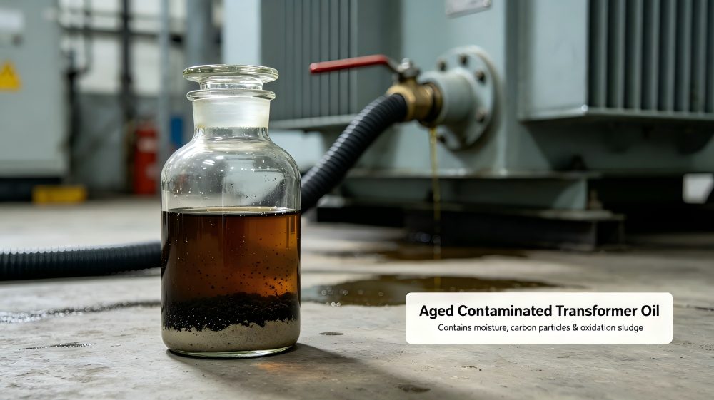
Oxidation Byproducts & Sludge: Thermal exposure in the presence of oxygen catalyzes oil oxidation, forming acidic compounds, peroxides, and insoluble sludge. Sludge settles on winding surfaces and inside cooling ducts, acting as a thermal insulator that blocks oil flow, elevates operating temperatures, and accelerates systemic aging.
Transformer Insulating Oil Lifecycle Diagram
The typical operational journey and degradation loop of transformer oil is structured as follows:
[Virgin / New Oil Ingestion] ➔ [Thermal & Electrical Exposure] ➔ [Contamination: Water, Gases, Particles] ➔ [Oxidation & Acid Formation] ➔ [Sludge Precipitation & Cellulose Decay] ➔ [Dielectric Breakdown / Transformer Failure]
Implementing an aggressive vacuum transformer oil purifier maintenance regime interrupts this decay loop at the contamination stage, resetting the oil to a near-virgin dielectric state and preserving solid insulation.
How Transformer Oil Becomes Contaminated
Contamination arises from both external environmental sources (extrinsic) and internal thermal/electrical degradation processes (intrinsic). Understanding these entry pathways is critical for effective transformer oil maintenance.
- Breathing System Ingress: Open-breathing transformer designs exchange air with the atmosphere as temperature fluctuations cause oil expansion and contraction. Faulty desiccant breathers (e.g., saturated silica gel) pull moisture-laden air directly into the expansion tank.
- Paper Insulation Hydrolysis: Thermal degradation of paper insulation (cellulose, C6H10O5) releases water and carbon oxides into the oil as chemical sub-products of cellulose chain cleavage.
- Localized Thermal Overheating: Hot spots caused by stray flux, core overloading, or high-resistance connections thermally break down oil hydrocarbon molecules (CnH{2n+2}), producing combustible gases.
- Electrical Arc Discharges: High-energy spark arcs and localized partial discharges break chemical bonds in the oil, yielding elevated trace quantities of Acetylene (C2H2) and Hydrogen (H2).
- Maintenance & Commissioning Contamination: Uncontrolled exposure during tank unsealing, bushing replacements, oil sampling, or fluid topping-off introduces ambient atmospheric humidity, dust, and particulate debris.
- Transportation & Storage Contamination: Storing oil in unsealed drums or transferring fluid through non-dedicated, uncleaned hoses introduces moisture condensation, rust, and foreign chemical contaminants.
Contamination Flowchart
External Drivers: (Atmospheric Humidity, Breather Leaks, Transport) ──➔ Oil Matrix ── Internal Drivers: (Paper Aging, Arcing, Thermal Hot Spots, Particulates)
Both ingress pathways converge within the transformer tank, degrading dielectric integrity and accelerating solid paper insulation decay.
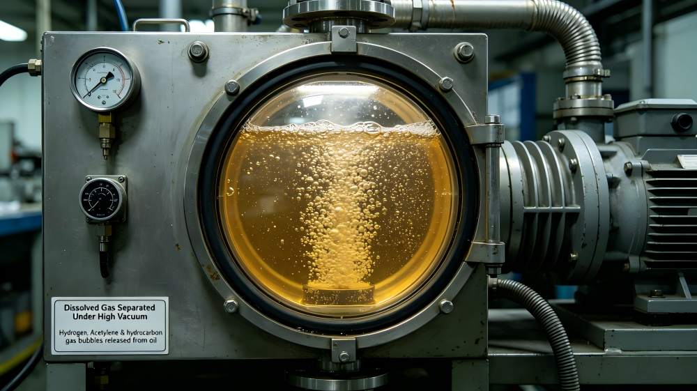
Major Contaminants in Transformer Oil
The table below categorizes the primary contaminants found in transformer oil, their root sources, and their specific impacts on transformer operational safety and dielectric performance.
| Contaminant | Primary Source | Operational & Dielectric Impact |
| Water / Moisture | Atmospheric breathing, paper thermal decomposition | Severe drop in BDV; accelerates paper hydrolysis; risk of bubble formation. |
| Air / Oxygen | Breathing system leakage, unsealed flanges, maintenance | Catalyzes oil oxidation; generates organic acids, peroxides, and insoluble sludge. |
| Hydrogen (H2) | Low-energy partial discharge (PD), electrolysis, water reaction | Indicator of internal PD; lowers flashpoint; signaling dielectric stress. |
| Acetylene (C2H2) | High-energy electrical arcing, localized intense spark breakdown | Critical indicator of severe active fault; high explosive and breakdown risk. |
| Carbon / Soot | Arcing, load tap changer (LTC) operation, severe thermal faults | Increases fluid electrical conductivity; creates conductive bridging paths. |
| Dust & Fibers | Environmental exposure, cellulose insulation wear | Provides nucleation points for electrical breakdown; reduces impulse strength. |
| Sludge | Advanced hydrocarbon oxidation, heavy polymer formation | Coats windings; blocks radiator cooling ducts; causes severe thermal runaway. |
Why Dirty Oil Damages Transformers
Operating a transformer with degraded or dirty insulating fluid triggers a compounding cascade of mechanical, thermal, and electrical degradation mechanisms:
- Reduced Dielectric Breakdown Voltage: Moisture and micro-particles act synergistically under intense localized electric fields, forming polarized conductive chains. This reduces dielectric breakdown strength by up to 80%, exposing high-voltage windings to catastrophic short circuits.
- Accelerated Cellulose Paper Aging: Solid pressboard paper provides over 90% of a transformer’s mechanical insulation strength. Water content in oil transfers into the paper insulation seeking equilibrium. Moisture levels above 3% in paper accelerate thermal hydrolysis degradation by a factor of 10x to 20x, permanently ending the asset’s structural life.
- Thermal Dissipation Impedance: As oxidation progresses, insoluble sludge deposits directly onto the transformer core, winding conduits, and radiator cooling channels. Sludge restricts convective oil circulation, creating thermal hot spots that compound dielectric stress.
- Increased Flashover and Explosive Arc Risk: High concentrations of dissolved combustible gases (H2, C2H2, CH4) lower the flashpoint and fire point of the insulating oil. Under severe transient overvoltage conditions, gas phase separation can cause violent intra-tank explosions and fire hazards.
[CRITICAL ASSET FACT] Solid paper insulation cannot be replaced in the field—once paper DP (Degree of Polymerization) drops below 200, the transformer has reached end-of-life. Protecting paper insulation through continuous transformer oil dehydration and purification is the single most cost-effective lifecycle intervention available.
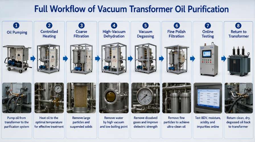
Transformer Oil Purification Process
Achieving total fluid restoration requires a systematic, multi-stage engineering workflow utilizing a specialized high-vacuum transformer oil purification machine.
Step-by-Step Purification Workflow
Step 1: Oil Extraction & Pumping: Contaminated oil is drawn from the transformer bottom valve via a dedicated positive-displacement or magnetic-drive pump designed to prevent cavitation.
Step 2: Controlled Heating: Oil enters an indirect electric heater with low surface power density (<1.5 W/cm²) to raise fluid temperature safely to 50°C – 65°C. Correct heating decreases oil viscosity and water surface tension without inducing thermal cracking.
Step 3: Primary Coarse Filtration: The warm fluid passes through a washable magnetic strainer and coarse filter mesh (typically 80–100 μm) to capture large rust scale, metal turnings, and coarse suspended solids.
Step 4: High-Vacuum Thermal Dehydration: Heated oil is sprayed or distributed into a high-vacuum chamber operated at pressures below 1 to 3 mbar. The combined low pressure and elevated temperature drop water’s boiling point, converting free, emulsified, and dissolved water into vapor.
Step 5: Vacuum Degassing & Separation: Utilizing high-surface-area Raschig rings or multi-stage thin-film dispersion trays, dissolved light-hydrocarbon gases (H2, C2H2, CH4) and air are flashed off and pulled into external condensers by auxiliary vacuum pumps.
Step 6: Fine Polish Filtration: Dehydrated and degassed oil passes through absolute micro-filter cartridges (down to 1 μm or 0.5 μm) to trap microscopic carbon soot and sub-micron particulate matter.
Step 7: Online Quality Testing & Inspection: Purified oil passes inline sensors monitoring dielectric breakdown strength, moisture content (ppm), and particle count before re-entering the system.
Step 8: Return to Transformer Tank: Purified oil is returned to the top of the transformer tank or recirculated into storage under negative vacuum or positive nitrogen blanket pressure.
Filtration vs. Purification vs. Regeneration vs. Replacement
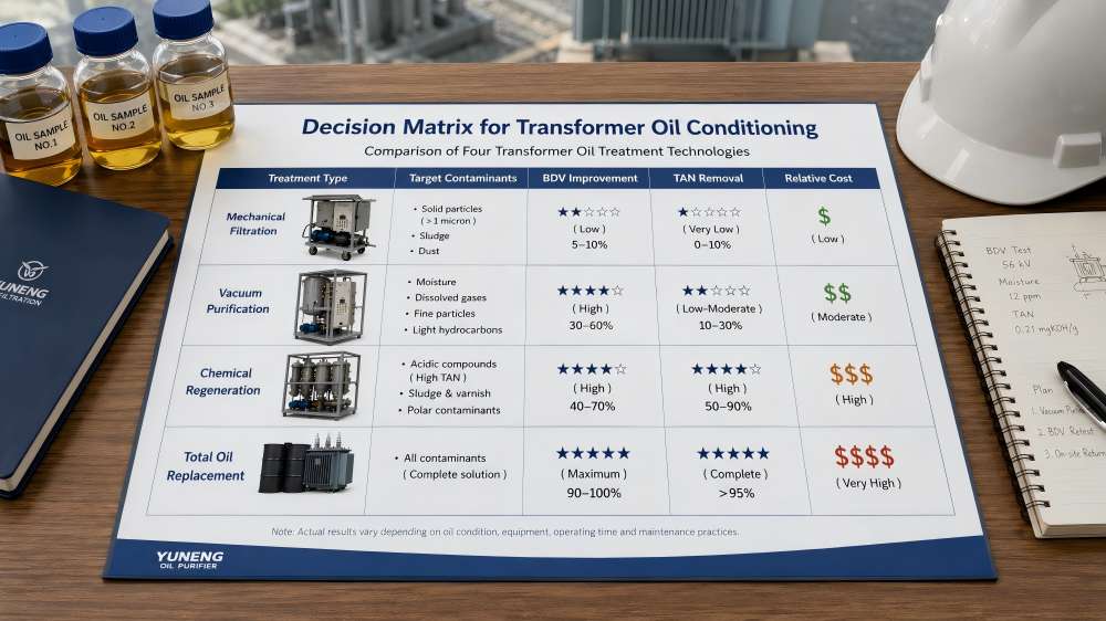
Industry terminology surrounding oil conditioning is frequently misused. The table below clarifies the technical scope, operational capabilities, and economic profiles of the four primary oil maintenance strategies.
| Process Method | Target Contaminants | Dielectric Impact | Acid / Color Removal | Relative Cost |
| Mechanical Filtration | Free particles, large sludge chunks, free water drops | Moderate improvement in BDV; leaves dissolved moisture/gases intact | No effect on acid or color | Very Low ($) |
| Vacuum Purification | Dissolved water, free/emulsified water, dissolved gases, fine particles | Restores BDV to > 70 kV; completely removes dissolved moisture & gas | Minimal effect on total acid number (TAN) | Moderate ($$) |
| Chemical Regeneration | Oxidation products, acids, polar compounds, sludge precursors, color | Restores original virgin oil dielectric, chemical & thermal properties | Reduces TAN < 0.01 mg KOH/g; restores clear color | Moderate-High ($$$) |
| Total Fluid Replacement | All existing oil contamination eliminated by complete replacement | Restores baseline properties (Note: leaves old residual sludge in core) | Complete replacement of active oil volume | Very High ($$$$) |
Decision Logic Matrix for Maintenance Strategy
- If BDV is low (<30 kV) but moisture and acid are normal ➔ Mechanical Oil Filtration.
- If moisture > 20 ppm or dissolved gases are present, but TAN < 0.1 mg KOH/g ➔ Vacuum Transformer Oil Purification.
- If Total Acid Number (TAN) > 0.15 mg KOH/g, oil color is dark brown/black, or sludge is present ➔ Transformer Oil Regeneration.
- If oil shows chemical contamination, PCB presence, or extreme oxidation with severe dielectric collapse ➔ Total Oil Replacement.
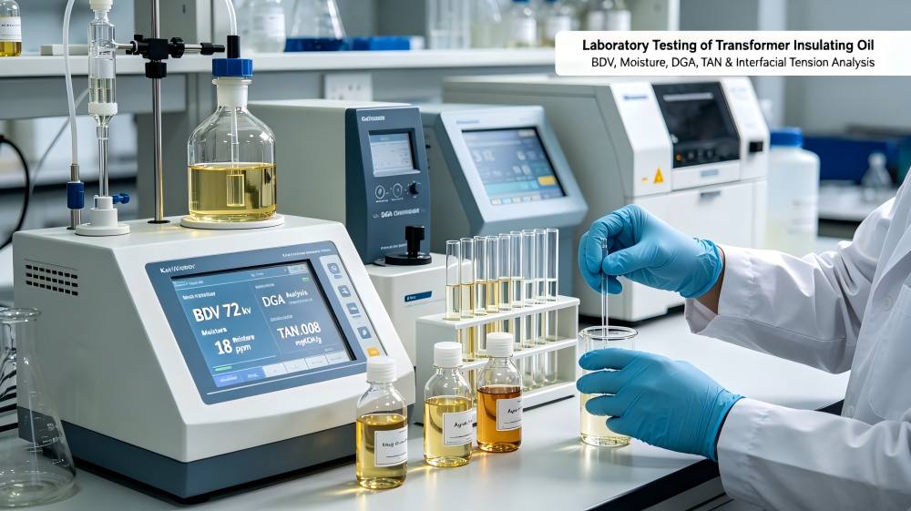
Transformer Oil Testing Key Parameters
Effective oil management relies on standard laboratory analytical techniques to evaluate fluid health prior to and following treatment:
- Breakdown Voltage (BDV): Measures dielectric voltage tolerance across a standard electrode gap (2.5 mm). High-voltage transformers require BDV > 60–70 kV.
- Moisture Content (PPM): Measured via Karl Fischer Coulometric Titration. Maximum recommended threshold for EHV (>345 kV) equipment is < 10 ppm.
- Total Acid Number (TAN): Quantifies acidic compounds resulting from oil oxidation (expressed as mg KOH/g). Values > 0.15 indicate imminent sludge formation risk.
- Interfacial Tension (IFT): Measures molecular attractive forces between oil and water (dynes/cm). A drop in IFT (<20 mN/m) signals accumulating soluble polar contaminants and decay products.
- Particle Counting (ISO 4406): Quantifies suspended particulate distribution per milliliter across micron ranges (≥4μm, ≥6μm, ≥14μm).
- Color & Appearance (ASTM D1500): Visual and optical scale rating from 0.5 (clear virgin oil) to 8.0 (severely degraded dark fluid).
- Specific Resistance (Resistivity): Evaluates fluid electrical insulation quality at room and elevated temperatures (90°C). High resistivity indicates clean oil free of ionic impurities.
- Dielectric Dissipation Factor (Tan Delta / DDF): Measures dielectric power loss within the oil. Elevated DDF indicates presence of moisture, polar soluble contaminants, or conductive micro-particles.
- Dissolved Gas Analysis (DGA): Gas Chromatography identification of fault gases (H2, CH4, C2H2, C2H4, C2H6, CO, CO2) to diagnose active thermal or electrical transformer faults.
International Standards Reference Guide
Compliance with global standardized practices ensures high quality and safety during oil evaluation and processing.
| Standard Ref. | Issuing Body | Scope & Technical Description |
| IEC 60422 | IEC | Supervision and maintenance guide for mineral insulating oils in electrical equipment. |
| IEC 60296 | IEC | Specifications for unused mineral insulating oils for transformers and switchgear. |
| ASTM D1816 | ASTM | Standard test method for dielectric breakdown voltage of insulating liquids using VDE electrodes. |
| ASTM D877 | ASTM | Standard test method for dielectric breakdown voltage of insulating liquids using disk electrodes. |
| ASTM D1533 | ASTM | Standard test method for water in insulating liquids by Coulometric Karl Fischer Titration. |
| ASTM D974 | ASTM | Standard test method for acid and base number by color-indicator titration. |
| ASTM D1500 | ASTM | Standard test method for ASTM color of petroleum products (ASTM Color Scale). |
| IEEE C57.106 | IEEE | Guide for acceptance and maintenance of insulating oil in equipment. |
Transformer Oil Purifier Components
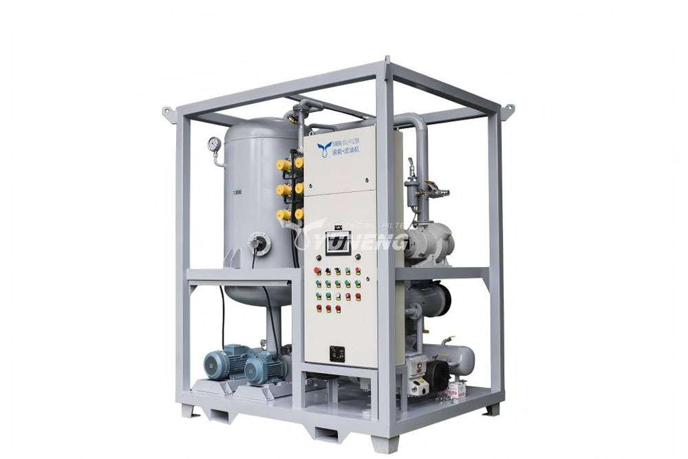
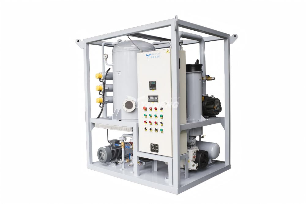
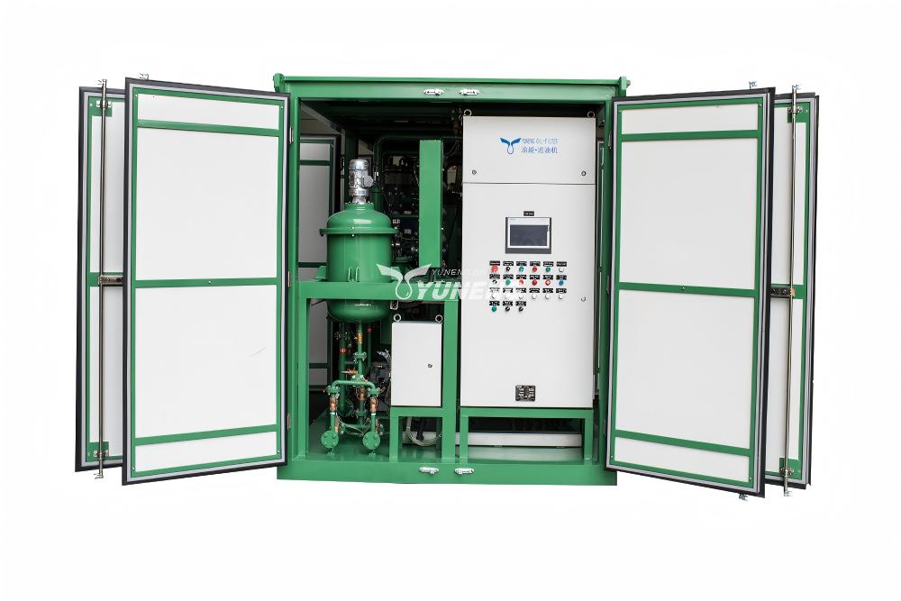
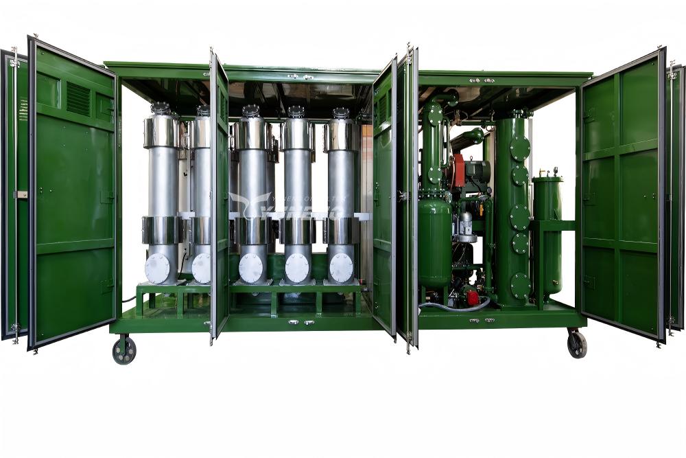
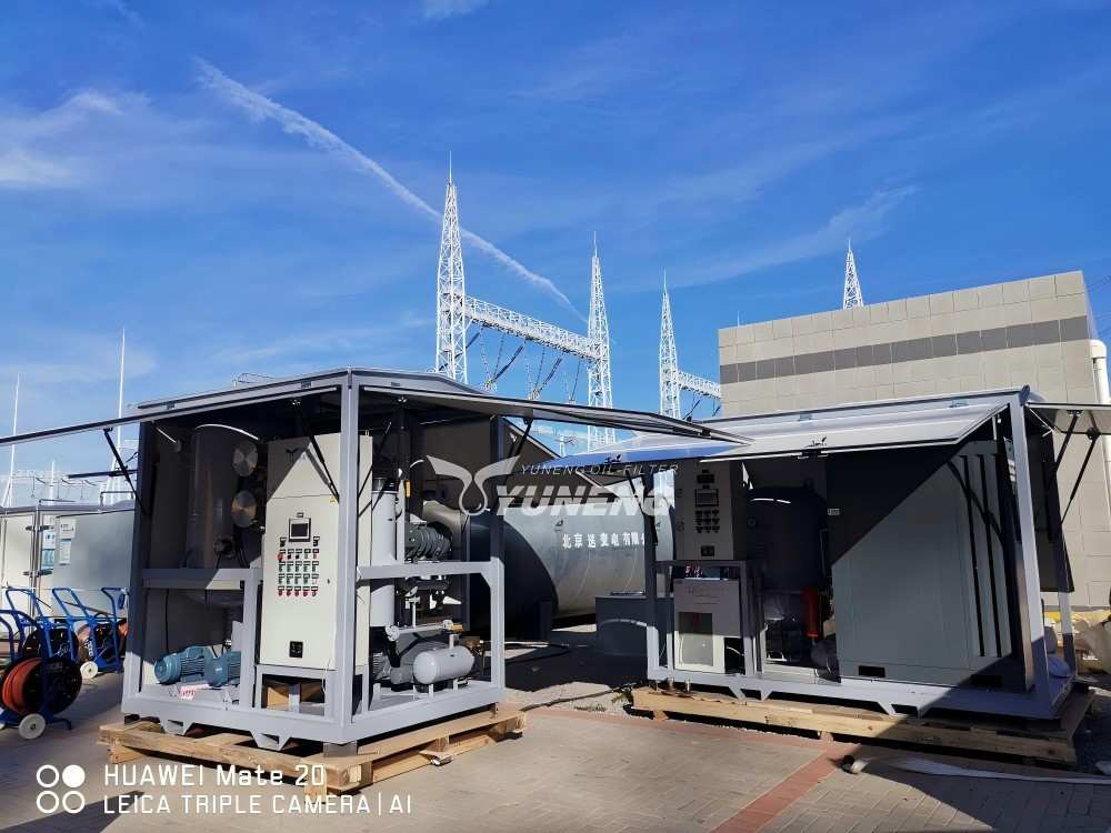
A high-efficiency vacuum transformer oil purifier integrates several mechanical, thermal, and electronic control sub-systems into a modular plant skid:
- Vacuum Separation Chamber: High-pressure vessel equipped with 316L stainless steel Raschig rings or multi-layer coalescing plates designed to maximize liquid surface area flash exposure.
- Indirect Heating System: Step-controlled electrical heaters utilizing low surface watt-density (<1.2 W/cm²) elements linked to PID temperature regulators to prevent localized oil thermal cracking.
- Primary Vacuum Pump System: Rotary vane or dry screw vacuum pump maintaining system baseline vacuum levels down to 1 mbar.
- Roots Booster Blower Pump: Mechanical booster pump operated in series with primary vacuum pumps, expanding total air evacuation capacity to achieve high vacuum ranges (<0.1 mbar) for EHV plant processing.
- Multi-Stage Filtration Assembly: Series arrangement of coarse magnetic pre-filters, medium coalescing units, and high-dirt-holding fine polish cartridges (1 μm absolute rating).
- Condenser & Refrigeration Unit: High-efficiency heat exchanger and chilling loop that cools liberated moisture vapors into liquid condensate before reaching vacuum pumps.
- PLC Control & Automation Interface: Programmed Logic Controller with touch-screen HMI managing automated oil level control, anti-foaming optical sensors, over-pressure interlocks, and inline fluid diagnostics.
Physics of Vacuum Dehydration
Vacuum dehydration operates on Line’s Law and the fundamental thermodynamic principle that reducing ambient vapor pressure lowers the boiling point of liquid water. At atmospheric pressure (1013 mbar), water boils at 100°C. Inside a high-vacuum chamber operated at 1 mbar, water boils and flashes into steam at approximately -6°C.
The Three States of Water in Oil
- Free Water: Undissolved water droplets suspended or settled at the bottom of the tank due to density differences (1.0 g/cm3 vs 0.88 g/cm3). Removed easily via mechanical coalescence or gravitational separation.
- Emulsified Water: Stable microscopic water droplets suspended in an emulsion with oil molecules, caused by shear stresses and polar oxidation byproducts. Requires thermal energy and coalescing filters to break.
- Dissolved Water: Water bound molecularly within the liquid hydrocarbon matrix. Vacuum dehydration flushes dissolved moisture out by creating a vapor pressure differential between the liquid phase and gas vacuum interface.
Vacuum Degassing & Gas Extraction
Dissolved gas extraction follows Henry’s Law, which states that the quantity of a dissolved gas in a liquid is directly proportional to the partial pressure of that gas above the liquid surface.
When contaminated transformer oil is exposed to a ultra-low vacuum environment (<0.5 mbar) across a thin liquid film, partial pressure differential forces dissolved low-boiling-point hydrocarbon gases (Hydrogen, Methane, Ethylene, Acetylene) and atmospheric gases (Oxygen, Nitrogen) to immediately flash out of the liquid matrix. Efficient removal restores dielectric insulation, eliminates partial discharge risk, and re-establishes a clean baseline for future Dissolved Gas Analysis (DGA) diagnostic monitoring.
Multi-Stage Filtration Architecture
To protect internal vacuum components and prevent cartridge clogging, high-performance purification machines implement a progressive multi-stage mechanical filtration architecture:
- Stage 1 (100 μm Coarse Magnetic Strainer): Traps coarse scale debris, heavy sediments, and metallic particles, protecting the primary inlet gear pump.
- Stage 2 (20 μm Medium Pre-Filter): Removes suspended carbon particles, oxidized particulates, and coarse cellulose fiber flocs.
- Stage 3 (5 μm Coalescing & Particulate Element): Captures micro-particles and coalesces free and emulsified moisture droplets prior to vacuum chamber entry.
- Stage 4 (1 μm Absolute Fine Polish Cartridge): High-efficiency micro-glass fiber element filtering fine carbon soot and sub-micron particles to meet ISO 4406 clean class standards.
Oil Regeneration & Deacidification Technology
When transformer oil exhibits advanced chemical degradation (Total Acid Number > 0.15 mg KOH/g, dark color, low interfacial tension), standard vacuum degassing and dehydration are insufficient. The oil requires chemical regeneration (reclamation).
Comparative Reclamation Adsorbent Media
- Fuller’s Earth (Attapulgite Clay): Traditional active porous clay adsorbent containing magnesium-aluminum silicate. Highly effective at capturing polar acids, sludge precursors, oxidation products, and decay compounds. Requires spent clay disposal or high-temperature reactivatable systems.
- Activated Alumina (Al2O3): Synthetic porous aluminum oxide granules offering high acid adsorption capacity and mechanical stability. Used extensively in small-scale off-line bypass filter columns.
- Thermo-Chemical On-Line Reactivatable Columns: Advanced modern systems that utilize automated columns of Fuller’s earth. Once saturated with oil contaminants, the system automatically drains the column and initiates an in-situ high-temperature thermal reactivation cycle, burning off captured contaminants and restoring clay activity for up to 300 cycles without media manual replacement.
Online vs. Offline Purification Comparison
Selecting between online (energized transformer) and offline (de-energized asset) oil processing depends on system criticalities and site operational constraints.
| Parameter / Feature | Online Purification (Energized) | Offline Purification (De-Energized) |
| Power Outage Requirement | Zero system outage required; asset remains online | Requires scheduled system shutdown & safety isolation |
| Processing Safety Risk | Higher operational risk; requires safety interlocks | Low operational risk; completely safe for technicians |
| Cellulose Paper Drying | High efficiency; load vibration & heat helps pull paper water | Moderate efficiency; static oil temperature gradient |
| Combustible Gas Extraction | Requires cautious monitoring to avoid gas interpretation errors | Ideal environment for full degassing and restoration |
| Capital & Equipment Cost | Higher equipment cost (requires fail-safe PLC controls) | Lower equipment cost (standard machine configuration) |
| Typical Target Assets | Critical transmission transformers, continuous industrial process | Distribution transformers, planned overhaul outages |
Complete Standard Operating Procedure (SOP)
Executing transformer oil purification demands rigid adherence to safety and operational protocols:
- Pre-Operational Inspection & Safety Preparation: Establish safety perimeters, verify equipment grounding/earthing connections, check spill containment kits, and verify hose pressure ratings.
- Baseline Oil Sampling: Draw baseline oil samples from the transformer bottom sampling valve in accordance with ASTM D923. Test for baseline BDV, moisture, and DGA levels.
- Equipment Hydraulic Connection: Connect suction hose from transformer bottom drain valve to purifier inlet. Connect discharge hose from purifier outlet to transformer top valve/radiator header.
- Valve Alignment & Vacuum Priming: Open connection valves, prime system inlet lines, establish vacuum chamber negative pressure, and verify no vacuum leaks exist.
- System Startup & Controlled Heating: Energize oil circulating pump, activate indirect heating system, and gradually raise oil temperature to target operational range (50°C ~ 65°C).
- Vacuum Chamber Operation & Degassing: Engage Roots booster vacuum pump to achieve target operating vacuum (<1 mbar). Monitor oil level sight glass and anti-foam sensor controls.
- Continuous Operational Monitoring: Log operating parameters hourly: inlet/outlet oil pressure, vacuum level, heater temperature, moisture sensor output, and flow rate.
- Target Testing & Process Completion: Perform inline dielectric strength and moisture testing. Continue purification until oil meets target metrics (BDV > 70 kV, water < 10 ppm).
- Safe System Shutdown: De-energize heaters, allow oil to cool below 45°C, break vacuum with dry nitrogen gas, isolate oil valves, and safely drain connection hoses.
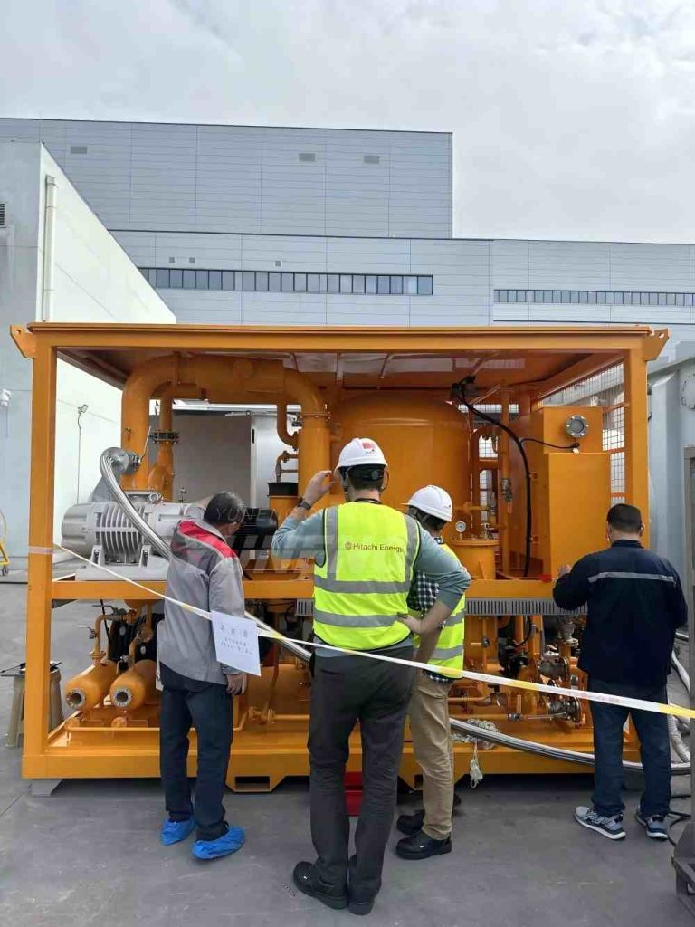
- Post-Treatment Sample & Final Documentation: Draw final post-treatment oil samples for lab certification. Record metrics in asset maintenance logs.
Purification Time & Pass Duration Calculations
The total duration required to process a transformer volume depends on oil volume, moisture concentration, system flow rate, vacuum efficiency, and fluid operating temperature.
Mathematical Pass Estimation Formula
To achieve high-spec dielectric purity, standard industry guidelines require passing the total system volume through the purifier between 3 and 5 volumetric passes.
Total Required Processing Time (Hours) = [Total Oil Volume (Liters) × Number of Passes (3 to 5)]/Purifier Flow Rate (Liters/Hour)
Example Operational Calculation
- Asset Parameters: 110 kV Transformer with 15,000 Liters of insulating mineral oil.
- Purifier Capacity: High-vacuum plant rated at 6,000 Liters/Hour.
- Target Requirement: 4 Complete Pass Cycles.
- Calculation: Total Hours = (15,000 L × 4 passes) / 6,000 L/hr = 10 Hours of continuous processing time.
Recommended Maintenance Schedule & Decision Matrix
Establishing routine oil monitoring schedules prevents unexpected transformer outages and extends equipment service life.
| Frequency | Key Maintenance Action Items | Target Threshold Standard |
| Monthly | Visual oil level check, inspect silica gel breather color, check for external flange leaks | Silica gel > 65% blue/amber; zero fluid leaks |
| Quarterly | Perform inline moisture sensor logging, verify operating temperature trends | Moisture rate of rise < 1 ppm/month |
| Annually | Comprehensive laboratory oil analysis: BDV, Moisture ppm, TAN, IFT, DGA testing | BDV > 50 kV (>69kV class); Water < 15 ppm |
| 3–5 Years | Preventive offline or online vacuum purification cycle for critical transmission units | Restore BDV > 70 kV; Water < 8 ppm |
| Condition-Based | Initiate immediate purification/regeneration if DGA indicates fault or BDV < 40 kV | Immediate intervention based on DGA limits |
Choosing the Right Transformer Oil Purifier
Selecting appropriate purification machinery requires evaluating specific operational, environmental, and technical factors:
- Transformer Capacity & Oil Volume: Match purifier flow rate ($L/h$) to total asset oil volumes. Standard capacities range from 1,000 L/h (distribution systems) up to 18,000 L/h (ultra-high voltage substations).
- Voltage Level Requirements: High-voltage (>220 kV) and EHV systems require double-stage high-vacuum purifiers (operating pressure <0.1 mbar with Roots booster pumps).
- Target Flow Rate: Ensure complete processing within operational maintenance outage windows.
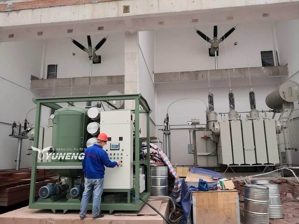
- Automation Level: Modern systems offer PLC controls, touch HMIs, automated foam control sensors, and automated inline oil quality diagnostics.
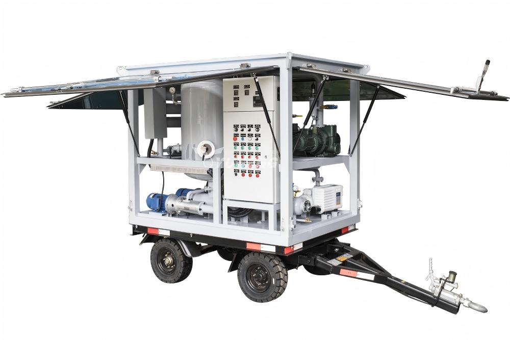
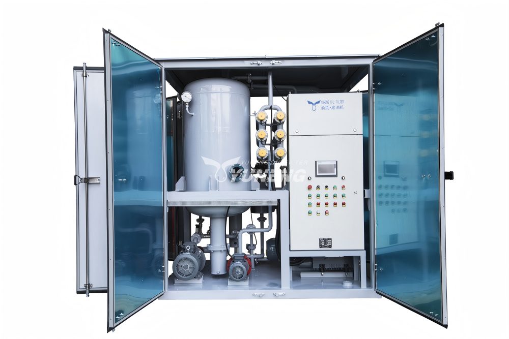
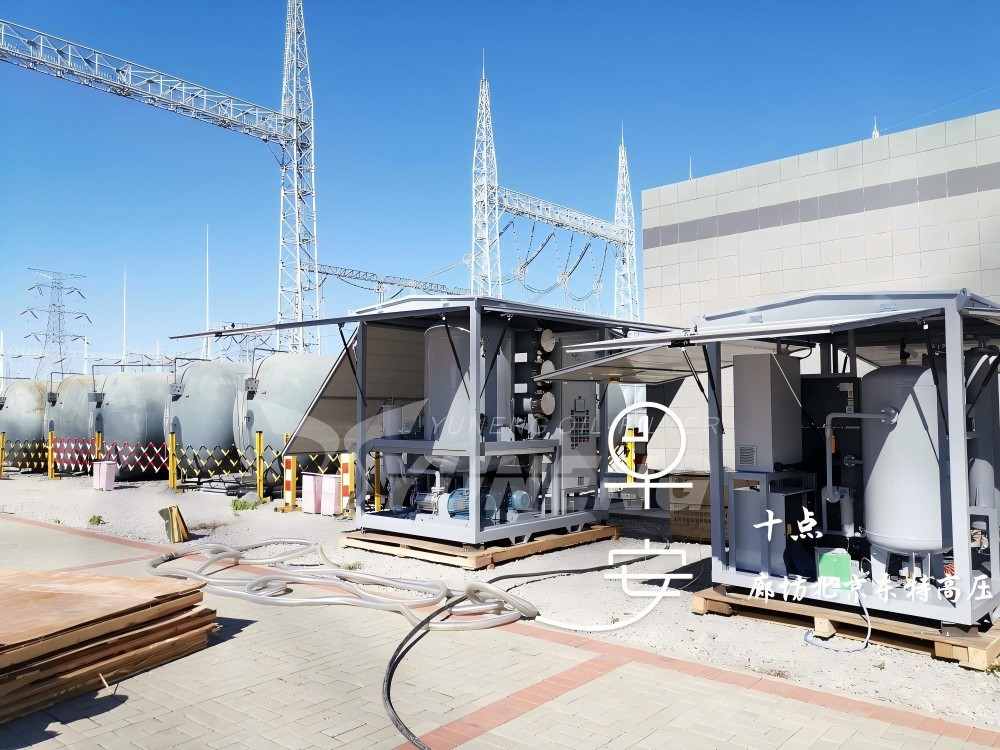
- Mobility & Enclosure: Choose between stationary shop skids, mobile road-ready trailer units, or weatherproof enclosed container configurations.
- Climatic & Altitude Considerations: High-altitude installations require oversized vacuum pumps to compensate for atmospheric pressure drop.
Cost Analysis & Return on Investment (ROI)
Investing in proactive transformer oil purification yields high financial returns compared to fluid replacement or emergency asset failure.
| Option / Strategy | Direct Financial Investment | Operational Downtime | Expected Asset Lifespan |
| Vacuum Oil Purification | Approx. $0.10 – $0.20 / Liter | Zero (Online) or 12 Hours | Extends service life by 10–15 years |
| Full Oil Replacement | Approx. $1.80 – $2.50 / Liter | 24–48 Hours total outage | Resets liquid insulation life |
| Catastrophic Failure | Exceeds $500,000 – $3,000,000+ | Weeks to months unplanned | Asset destroyed; collateral damage |
| [ROI SUMMARY] Purifying insulating fluid costs less than 10% of total oil replacement costs while avoiding long system outages, hazardous waste disposal liabilities, and catastrophic failure risks. | |||
Operational Troubleshooting Guide
The table below details common field operational issues encountered during oil processing, along with root cause analyses and corrective actions.
| Observed Issue | Probable Root Cause | Recommended Corrective Action |
| Low BDV After Purification | Fine particle contamination; saturated post-filter elements | Replace fine filter cartridges (1 μm); perform additional pass. |
| High Residual Moisture | Insufficient heating temperature; vacuum pump efficiency drop | Verify heater setpoint (65°C); inspect vacuum pump seals and oil. |
| Slow Vacuum Pull-down | System vacuum leak; moisture saturated in condenser coil | Perform vacuum leak test; drain water from condensing trap. |
| Severe Oil Foaming | Excessive moisture flashing; high inlet oil flow rate | Reduce inlet flow rate; adjust anti-foam optical sensor control. |
| Rapid Filter Clogging | Heavy sludge presence or extreme carbon soot in oil | Pre-filter oil using coarse mechanical separator before fine pass. |
| Acid Level Unchanged | Vacuum purifier used instead of chemical adsorbent media | Integrate Fuller’s earth or alumina regeneration column skid. |
| Dissolved Gas Not Reduced | Insufficient high vacuum depth (<1 mbar) or low oil temp | Engage Roots booster vacuum pump; ensure oil temperature is 60°C. |
Industry Applications
Insulating fluid purification is essential across critical industrial sectors:
- Electric Power Utilities: Transmission and distribution substations maintaining asset reliability and grid stability.
- Thermal & Hydro Power Plants: Step-up generator transformers (GSU) operating under continuous full-load conditions.
- Renewable Energy (Wind & Solar Generation): Step-up transformers subject to thermal cycling and environmental humidity.
- Heavy Industrial Manufacturing (Steel Mills & Foundries): Arc furnace transformers exposed to extreme electrical harmonics and load surges.
- Mining & Heavy Excavation: Subsurface and outdoor mobile substations exposed to severe dust, vibration, and moisture ingress.
- Electrified Railways & Transportation: Trackside traction substations requiring high uptime under variable load conditions.
- Petrochemical Processing Refineries: Hazardous area plants requiring explosion-proof purifiers to process critical infrastructure transformers.
- Data Centers & Mission-Critical Facilities: Facilities requiring high operational continuity via online fluid purification.
Frequently Asked Questions (FAQ)
Q: How often should transformer oil be purified?
A: Standard utility practice dictates testing transformer oil annually. Vacuum purification should be executed every 3 to 5 years as preventive maintenance, or immediately if lab tests show BDV < 40 kV or water content > 20 ppm.
Q: Can old transformer oil be reused after purification?
A: Yes. Vacuum purification restores dielectric breakdown voltage, moisture levels, and gas content to virgin oil standards. If the oil is chemically degraded (high acid/sludge), chemical regeneration fully restores original properties, making fluid reuse entirely safe.
Q: What moisture level is acceptable in transformer oil?
A: Acceptable moisture levels depend on voltage rating. For Extra High Voltage (EHV > 345 kV) equipment, moisture must be < 10 ppm. For standard distribution transformers (11–33 kV), moisture levels up to 20–25 ppm are acceptable under IEEE C57.106.
Q: Is oil purification better than complete oil replacement?
A: Yes, in most scenarios. Purification costs 10% to 20% of replacement costs, avoids long system outages, eliminates hazardous waste disposal, and recycles existing oil while restoring original dielectric properties.
Q: What is the difference between oil filtration and oil regeneration?
A: Filtration and vacuum purification remove mechanical solids, dissolved moisture, and dissolved gases. Regeneration uses active adsorbent media (Fuller’s earth) to chemically remove organic acids, sludge, and decay products, restoring dark oil to its original clear yellow color.
Q: Can vacuum purification remove acidity from oil?
A: No. Vacuum purification removes water, air, and dissolved hydrocarbon gases, but has minimal effect on soluble organic acids. Removing acidity requires chemical regeneration using clay adsorbents or active alumina.
Q: How long does transformer oil purification take?
A: Purification duration depends on oil volume and unit capacity. Typically, complete processing requires 3 to 5 volume passes, taking between 8 and 16 hours for standard power transformers.
Q: Can purification improve low Breakdown Voltage (BDV)?
A: Yes. Removing microscopic suspended particles, carbon soot, and dissolved water through vacuum purification routinely elevates BDV from low levels (<25 kV) to above 70 kV.
Q: What transformer sizes require online purification systems?
A: Online purification is recommended for critical transmission assets (110 kV, 220 kV, 500 kV), large generator step-up transformers, and mission-critical continuous process facilities where power shutdowns are economically unacceptable.
Q: How do I choose the right oil purifier?
A: Evaluate transformer voltage rating, total oil volume, required mobility (trailer vs skid), climate conditions, and level of PLC automation. Select a machine flow rate ($L/h$) capable of completing 4 total passes within your scheduled maintenance window.