How to Size a Dry Air Generator for Transformer Maintenance
Table of Contents
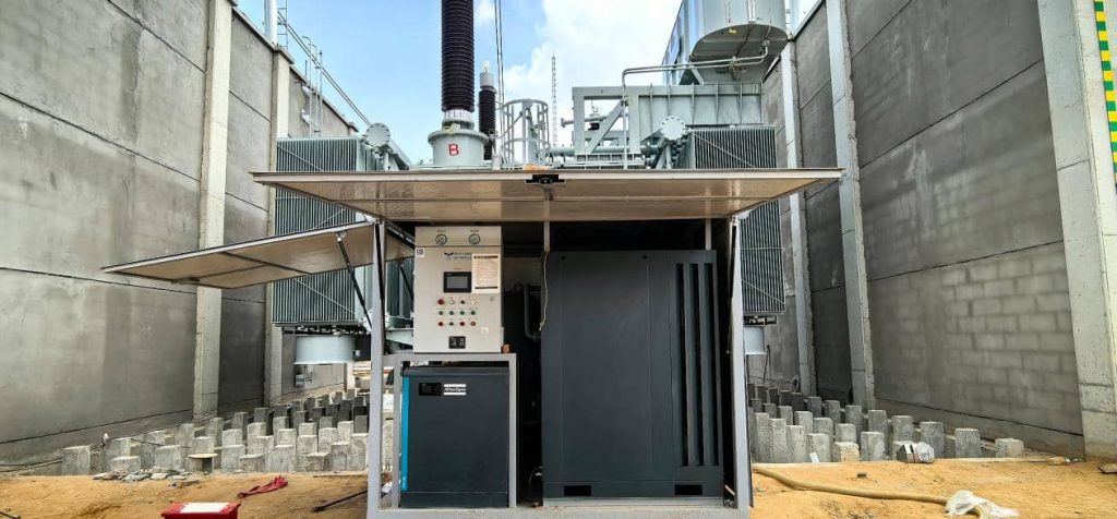
During installation and during inspection or overhaul of a transformer, the core and insulation may be exposed to surrounding air. Moisture ingress can degrade insulation condition and increase the likelihood of moisture-related issues. Low dew point air is supplied from a dry air generator to assist in maintaining a controlled environment during these operations. However, specifying a generator by transformer MVA can cause you to select the wrong equipment.
Transformers with the same rating can have different tank sizes, air connections, maintenance requirements, and airflow needs. A unit that’s too small might not provide the required flow at the point of use. An oversized unit will raise purchase and operating costs with no practical benefit.
The actual maintenance task is the starting point for effective transformer dry air generator sizing. The engineers need to evaluate the simultaneous airflow demand, delivery pressure, pipeline losses, outlet air quality, and the anticipated operating period before choosing the model.
What Determines the Required Dry Air Generator Flow Rate?
There are several factors that affect the required airflow. They should be assessed as a group and not in isolation.
1. Transformer setting and maintenance task
Tank volume is good background information, but does not directly determine the required generator capacity.
For example, backfilling a transformer tank after vacuum treatment may require a different flow than supplying dry air to maintain a protective atmosphere. The sizing method should be based on the real process, including the needed air exchange rate and the duration of each operation.
2. Quantity of simultaneous supply points
List all connections which may require dry air during the same operating period. These could be transformer tank connections and temporary supply lines listed in the maintenance procedure.
Estimate the demand at each point and add the simultaneous requirements of flow. Do not just add up the maximum rating of each connection to get total demand if they will not be operating at the same time. Also think about leaks, temporary hookups and changes in demand as maintenance goes on.
3. Dew point and quality of outlet air required
The flow rate is just one part of the equipment specification. The generator must also supply air meeting the dew point, cleanliness and oil content requirements of the project.
Verify that the manufacturer’s performance figures apply at the required flow and operating conditions. A low dew point measured under one set of conditions does not guarantee the same performance at all flow rates.
For the separate question of choosing a target dew point, please see YUNENG’s guide to transformer dry air generator dew point selection.
4. Pipeline resistance and operating pressure
A generator must provide sufficient airflow at the transformer connection, not just at its own outlet.
Hoses, filters, valves, bends and small diameter pipes may add to pressure losses. Long delivery lines can also affect the pressure available at the point of use. Check the full delivery route. Check the required pressure, line diameter, hose length, fittings and pressure drop across the equipment.
5. Duty cycle and maintenance window
A project with a short outage window may require a different operating strategy than one with flexible scheduling. Determine whether demand is continuous or intermittent, and whether several outlets will operate simultaneously.
The selected generator must be capable of providing the required flow during the intended operating cycle, and not just during a short test under ideal conditions.
How to Calculate the Required Dry Air Flow
A reliable sizing process starts with an estimation of the demand and ends with a technical performance check.
Step 1: Find simultaneous demand
Observe the required airflow and the expected operating period for each supply point. Decide which links will be up at any given time. The preliminary total demand is the sum of the flow requirements of all simultaneously working outlets.
If changes in demand occur during maintenance, the main operating scenarios are calculated separately. This helps to establish the highest believable demand rather than assuming an unrealistic worst-case.
Step 2: Define a justified design flow
A rough design estimate can be obtained using the following relationship:
Design flow = Simultaneous demand × (1 + design margin)
Should include documented uncertainty, expected leakage, operating variability, and consequences of insufficient supply. Don’t just throw in a random percentage without an engineering basis.
This estimate is just a starting point and not a full sizing calculation. It is not a substitute for pressure drop analysis or verification of the rated performance of the generator.
Step 3: Check flow at actual operating conditions
Compare calculated design flow against the manufacturer’s rated capacity. Check the flow rating reference conditions and if the equipment can provide the required flow at the required pressure.
If the system contains long hoses or multiple fittings, check the pressure at the end connection. If the performance data do not extend to the proposed operating conditions, request a technical review by the manufacturer.
A suitable generator must be able to meet the requirements of the airflow, pressure, and the outlet air quality simultaneously. You can’t just select a model based on its flow rating.
How to Select the Right Dry Air Generator Model
Once the demand has been calculated, compare equipment using consistent technical criteria.
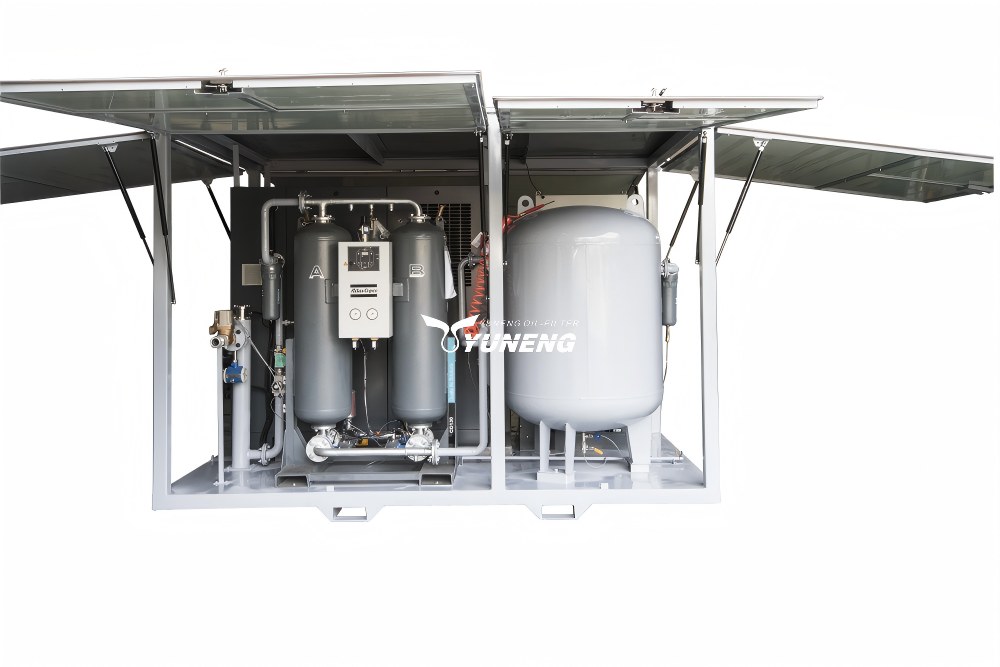
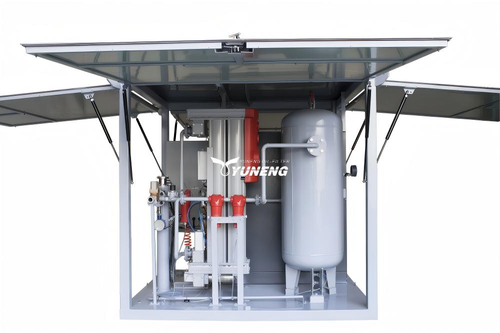
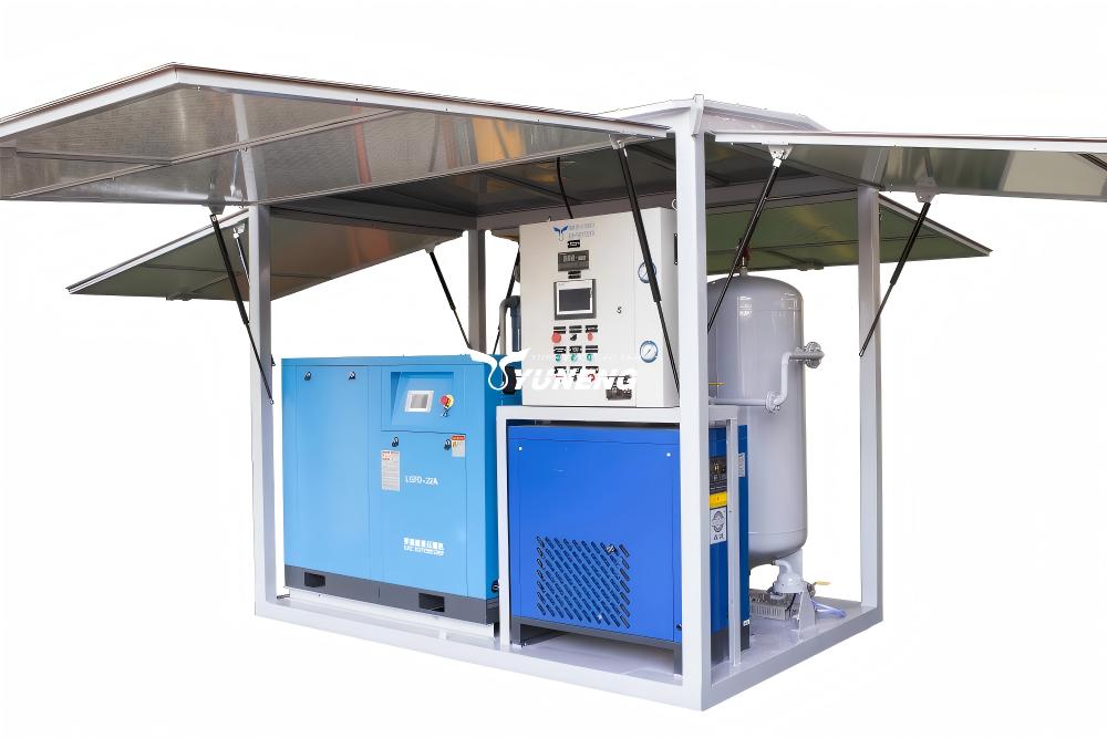
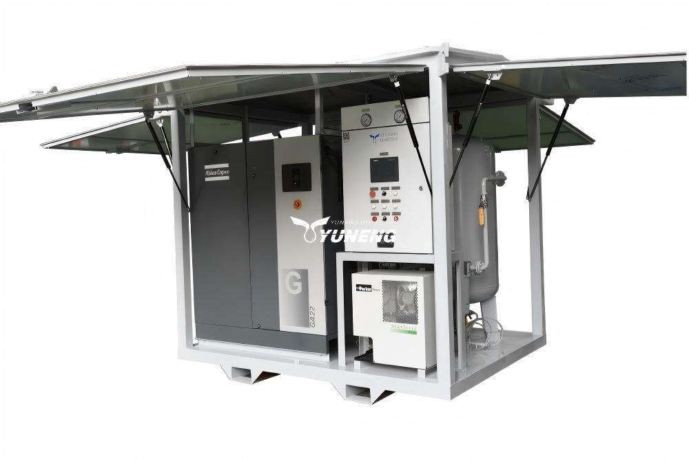
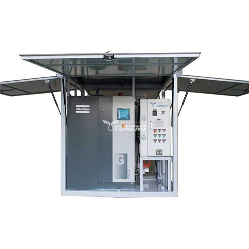
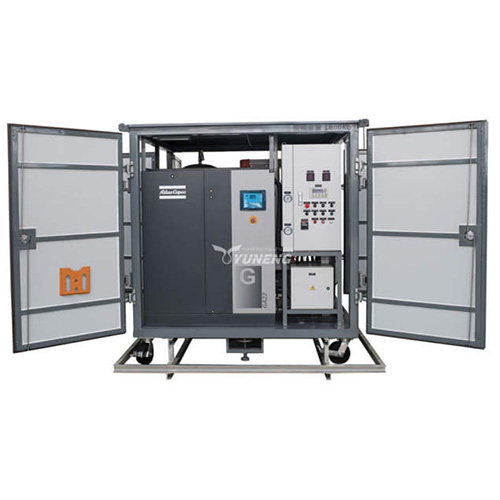
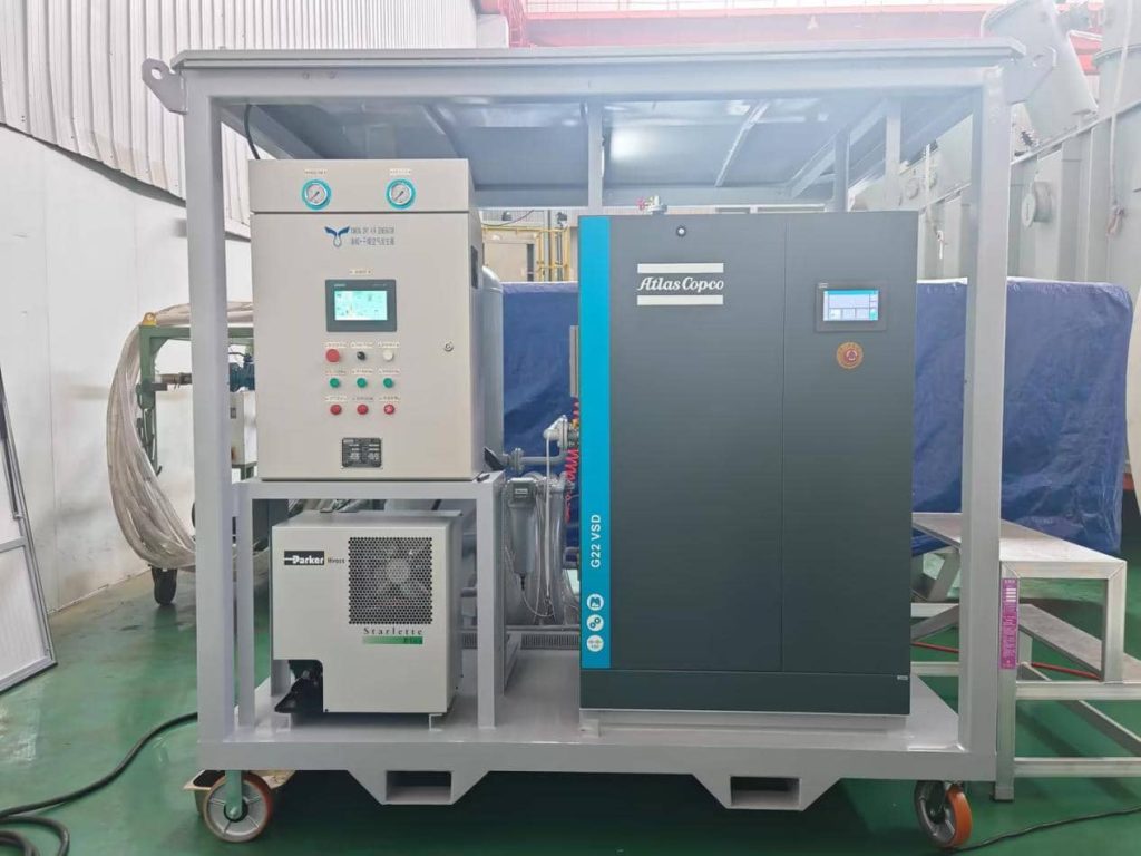
YUNENG’s GF series hot dry air generators offer several nominal flow capacities. The published specifications list GF-50, GF-100, GF-150, and GF-200 models with rated flows of 50, 100, 150, and 200 m³/h, respectively. Confirm the current specifications and availability of higher-capacity configurations directly with the manufacturer.
| Selection parameter | What buyers should verify |
| Rated airflow | Whether the capacity meets the calculated design demand |
| Flow reference conditions | How the stated flow is measured and rated |
| Working pressure | Whether the equipment suits the site’s operating requirements |
| Pressure drop | The loss through the generator and delivery system |
| Outlet dew point | Whether the specified performance meets the project requirement |
| Air cleanliness | Required particle and oil-content limits |
| Duty cycle | Suitability for the planned operating duration |
| Site requirements | Power supply, connections, footprint, and mobility |
| Service support | Documentation, spare parts, maintenance access, and technical assistance |
Do not assign a model solely by transformer MVA or voltage class. These details help describe the project, but they cannot replace a flow calculation and performance review.
For large transformers, multiple supply points, or complex piping arrangements, provide the supplier with the maintenance procedure and connection layout. Request confirmation that the proposed configuration can meet the required conditions.
Common Dry Air Generator Sizing Mistakes
- Using transformer MVA as the only sizing criterion. Rated capacity does not directly define the airflow needed for a particular maintenance procedure. Start with the actual demand.
- Ignoring pressure loss. A generator with adequate nominal flow may not deliver enough air through an unsuitable pipeline. Check the full system from the outlet to the transformer connection.
- Comparing non-equivalent flow ratings. Suppliers may present capacity figures under different reference conditions. Confirm the rating basis before comparing offers.
- Focusing only on dew point. A low dew point is important, but the unit must also deliver sufficient airflow and pressure while meeting the required air-quality specification.
- Oversizing without justification. A larger unit may increase capital cost, power demand, and transport requirements. Use a design margin supported by the application rather than automatically choosing the largest model.
Dry Air Generator Sizing Checklist for RFQ
A complete request for quotation should include:
- Transformer type, rated capacity, and maintenance task.
- Number of supply points and expected simultaneous airflow demand.
- Required flow rate and the basis of calculation.
- Target outlet dew point and air-cleanliness requirements.
- Required operating pressure and acceptable pressure drop.
- Hose or pipe diameter, approximate length, and connection details.
- Ambient temperature and humidity at the worksite.
- Expected operating hours and duty cycle.
- Available electrical supply, mobility requirements, and installation space.
- Required technical documents, inspection records, acceptance criteria, and after-sales support.
The more complete the operating data, the more meaningful the equipment comparison. This also reduces the risk of selecting a model that meets the nominal flow requirement but cannot perform as expected on site.
Frequently Asked Questions
Q1: How do I calculate the required dry air generator flow rate?
Determine all outlets that are on simultaneously and sum their air requirements. Implement a justified design margin and check pressure losses and generator performance at the expected operating conditions.
Q2. Can you use the transformer MVA to determine the capacity of a generator?
No. Transformer MVA is insufficient. Sizing is affected by the maintenance method, tank configuration, connection layout, the simultaneous airflow demand and the outlet air requirements.
Q3: Does a lower dew point mean a bigger generator?
No, not by default. Flow capacity and dew point are different performance requirements, but both depend on equipment design and operating conditions. Check that the unit you have selected can meet the required dew point at the flow you require.
Q4. Why is pressure drop a consideration when choosing a generator?
Pressure drop reduces the pressure available downstream and may limit delivered airflow. When checking the system performance, the long hoses, narrow pipes, filters and fittings should be considered.