How to Calculate Transformer Oil Purification Capacity for a Real Project

Oil Purification & Vacuum Technology Expert
Table of Contents
The choice of a transformer oil purifier is not a question of purchasing a machine with the rated flow equal to the power rating of a transformer. Engineers need to determine the volume of oil to be treated, the time required to do so, and the actual operating conditions to be considered, as well as ensure that the equipment is capable of delivering the required oil quality within the allocated maintenance window.
A proper transformer oil purifier capacity calculation is based on the project data, not on a standard size of equipment. The same transformer power rating can have different oil volume, operating limits and treatment needs. A 6,000 LPH purifier may not be able to sustain that flow rate in all site conditions.
This guide shows how to calculate the required transformer oil filtration rate, convert the result into a nominal equipment capacity and evaluate whether a proposed system is suitable for a real project.
Identify the Project Data Required for Capacity Calculation
Before calculating the required flow rate, establish the operating conditions and treatment objectives. Incomplete input data can produce an attractive calculation that does not reflect the actual project.
| Required input | Symbol | Engineering purpose |
| Oil volume to be treated | V | Establishes the actual processing volume |
| Required processing turnovers | N | Defines the planned cumulative oil throughput |
| Available maintenance window | T | Sets the project time constraint |
| Setup and interruption time | Ts | Accounts for time unavailable for processing |
| Effective-flow factor | f | Estimates the relationship between rated and effective flow |
| Required final oil quality | — | Defines the treatment and verification objectives |
| Site piping and power conditions | — | Helps establish whether the proposed equipment can operate as intended |
The volume of oil shall be verified by means of the transformer documentation, oil inventory records or reliable measurements on site. Treating the volume to be treated as the total tank capacity of the transformer does not necessarily mean.
The goal of treatment is important as well. That’s different than dealing with oil that has been very aged or dealing with contamination that requires extra processes. Oil that is otherwise still serviceable can have moisture and particles removed from it. The number of processing turnovers required should therefore be determined by the results of the initial oil test, the project requirements, the treatment method and the expected endpoint. It is not to be regarded as a universal constant.
Calculate the Total Oil Processing Volume
The first calculation determines how much oil must pass through the purifier during the planned treatment.
Total processing volume:
Total Processing Volume = Oil Volume × Required Processing Turnovers
In mathematical notation:
Vp = V × N
Where:
- Vp is the cumulative processing volume in liters.
- V is the actual oil volume to be treated in liters.
- N is the planned number of processing turnovers.
For example, if a transformer contains 24,000 liters of oil and the project plan requires two volume turnovers, the cumulative processing volume is:
24,000 L × 2 = 48,000 L
The equipment must therefore process a cumulative volume of 48,000 liters to complete the planned two turnovers.
However, do not mistake cumulative throughput for physical oil inventory. Having a system that holds 24,000 liters process 48,000 liters of oil doesn’t mean the oil volume in the transformer has doubled. Instead, it signifies that the oil has completed the designed number of circulation cycles in the treatment system.
Turnover calculations are useful for preliminary planning, but they do not independently prove that the required moisture, dissolved gas, or particle levels will be achieved. Final treatment requirements must be confirmed through oil condition assessment and appropriate testing.
Calculate the Required Transformer Oil Filtration Rate
After establishing the cumulative processing volume, determine how much effective processing capacity is needed to finish within the available operating time.
Calculate the minimum effective flow rate
The basic formula is:
Required Effective Flow Rate = Total Processing Volume ÷ Effective Processing Time
Or:
Qeff = (V × N) ÷ Trun
Where:
- Qeff is the required effective flow rate in liters per hour.
- V is the oil volume in liters.
- N is the planned number of turnovers.
- Trun is the time actually available for processing, in hours.
Suppose the project requires 48,000 liters of cumulative processing within 10 hours of effective operation.
48,000 L ÷ 10 h = 4,800 L/h
The required effective flow rate is therefore 4,800 L/h.
This is the flow that the treatment operation needs to sustain, not necessarily the rated capacity that should appear on the equipment specification.
Convert effective flow into nominal equipment capacity
A purifier’s actual effective flow may differ from its rated flow because of operating conditions, piping resistance, filter condition, and equipment configuration.
If the estimated effective-flow factor is f, the preliminary rated-capacity requirement is:
Required Rated Capacity = Required Effective Flow Rate ÷ Effective-Flow Factor
Qrated ≥ (V × N) ÷ (Trun × f)
For example, if the required effective flow is 4,800 L/h and the assumed effective-flow factor is 0.85:
4,800 ÷ 0.85 ≈ 5647 L/h
The preliminary calculation indicates a rated capacity of approximately 5647 L/h or higher.
The 0.85 factor is an illustrative engineering assumption, not a universal industry value or a guaranteed performance figure for any YUNENG machine. For an actual project, the factor should be based on manufacturer performance data, comparable operating experience, or field measurements under representative conditions.
Where reliable data are unavailable, request a performance assessment from the equipment supplier instead of relying on an arbitrary allowance.
Account for the actual operating window
The total maintenance window is not always equal to the time available for oil processing.
If a project has a 12-hour maintenance window and requires two hours for equipment connection, preliminary checks, sampling, interruptions, and other non-processing activities, the effective processing time is:
12 h − 2 h = 10 h
Using the full 12 hours in the flow calculation would underestimate the required processing rate.
For this reason, project planners should separate equipment preparation, active treatment, quality verification, and other scheduled activities when preparing the work plan.
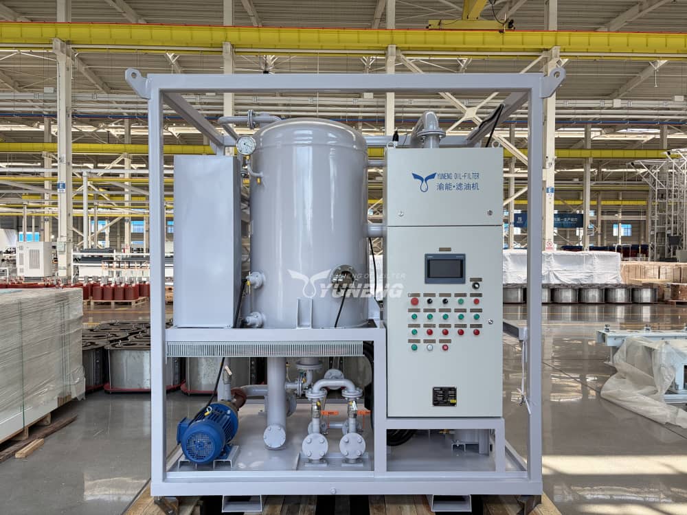
Worked Example: Calculate Capacity for a Transformer Project
Consider a hypothetical transformer maintenance project with the following requirements.
| Project parameter | Assumed value |
| Oil volume to be treated | 9,000 L |
| Planned processing turnovers | 2 |
| Total maintenance window | 12 h |
| Setup, sampling, and interruption allowance | 2 h |
| Effective processing time | 10 h |
| Assumed effective-flow factor | 0.85 |
These values demonstrate the calculation method only. They are not a universal treatment prescription or a statement of measured equipment performance.
Step 1: Calculate the cumulative processing volume.
9,000 L × 2 = 18,000 L
Step 2: Calculate the required effective flow rate.
18,000 L ÷ 10 h = 1,800 L/h
Step 3: Estimate the required rated capacity.
1,800 L/h ÷ 0.85 ≈ 2120 L/h
The preliminary equipment requirement is therefore approximately 2120 L/h or higher.
Step 4: Verify the available equipment.
Although a 6,000 LPH vacuum oil purifier may technically meet the calculated required flow, this is still only nominal and further evaluation is required to ensure the oil purifier is adequate to complete the work in the scheduled timeframe.
The supplier must verify that the proposed configuration can sustain the necessary effective flow under the expected oil temperature, viscosity, vacuum conditions, filter loading, and piping arrangement. The required final oil quality must also be achievable within the proposed operating plan.
If the verified effective flow is lower than expected, the project may require a longer processing window, a different equipment configuration, or an alternative treatment plan. This is the key difference between selecting a machine from its label and performing a defensible transformer oil purifier capacity calculation.
How Site Conditions Affect the Actual Filtration Rate
A calculated flow rate is only as reliable as the operating assumptions behind it. Several site conditions can affect actual throughput or extend the total project duration.
| Site condition | Potential impact | What engineers should verify |
| Oil temperature and viscosity | Changes pumping behavior and hydraulic resistance | Operating temperature, viscosity range, and supplier performance data |
| Hose diameter and length | Adds friction losses and may restrict flow | Hose dimensions, fittings, valves, and connection layout |
| Elevation difference | Can affect pump operating conditions | Inlet and outlet elevations and pump operating limits |
| Filter loading | Rising differential pressure may reduce throughput | Filter condition, pressure limits, and replacement criteria |
| Vacuum system performance | May affect moisture and gas removal rates | Working conditions, treatment temperature, and target oil quality |
| Power supply | May limit available heating or auxiliary equipment operation | Supply voltage, frequency, available power, and starting requirements |
| Sampling and testing | Adds time before final acceptance | Sampling schedule, laboratory turnaround, and acceptance criteria |
These factors should not be automatically translated to a single percentage reduction. Their effect depends on machine design, oil condition, process configuration and site layout. Thus, additional pressure drops may occur in the case of long hose arrangements and heavily loaded filter elements may require to be checked or replaced during operation. Some projects with very low moisture or dissolved gas requirements may also require more processing time even if the equipment can deliver its rated flow.
The most reliable approach is to obtain performance information for the intended operating conditions and confirm critical assumptions before finalizing the equipment specification.
Translate the Calculated Rate into an Equipment Specification
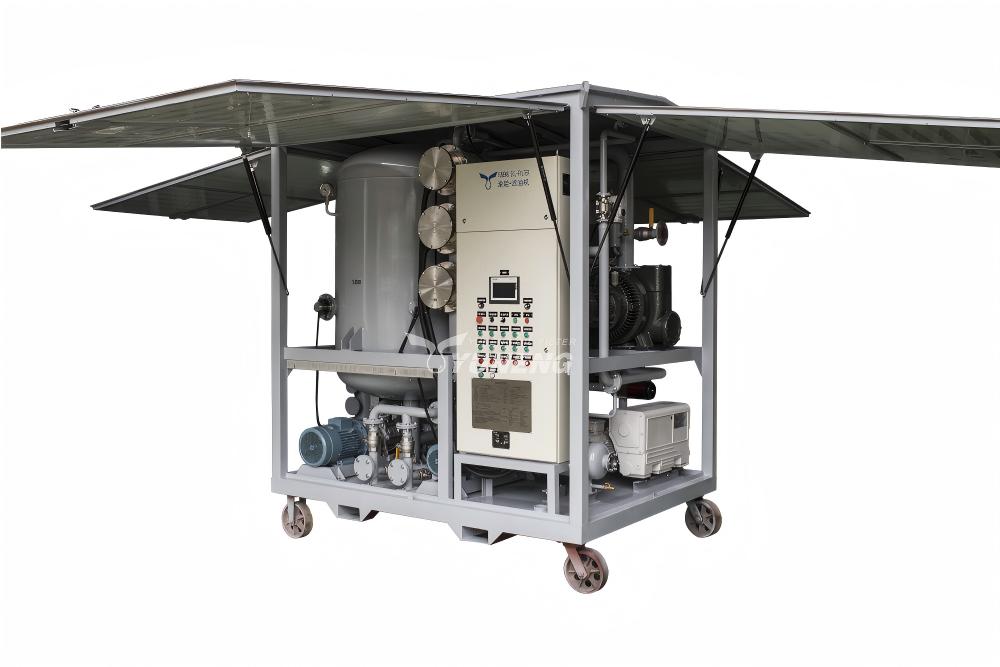
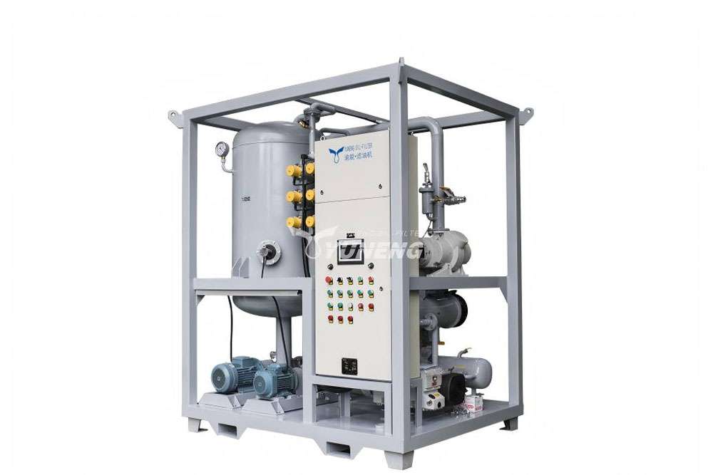
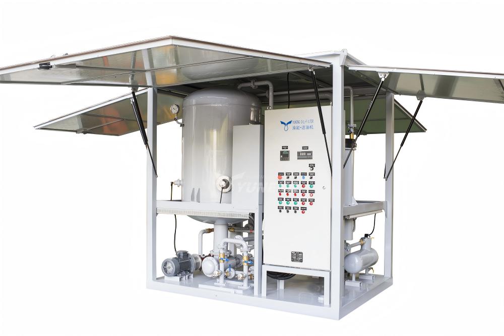
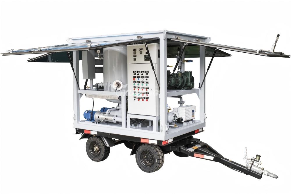
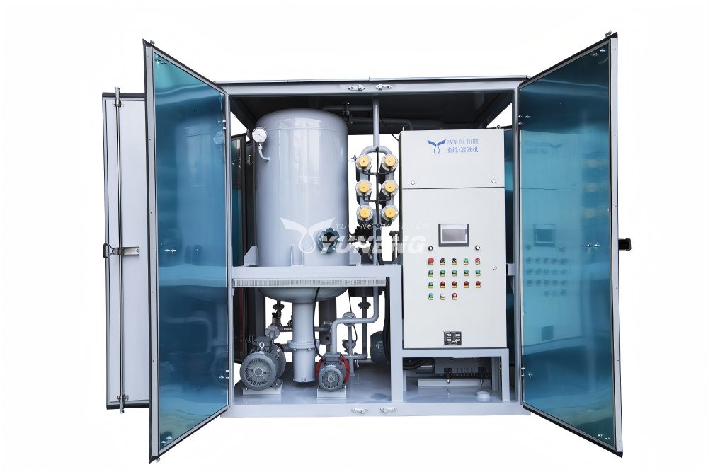
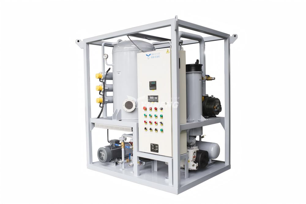
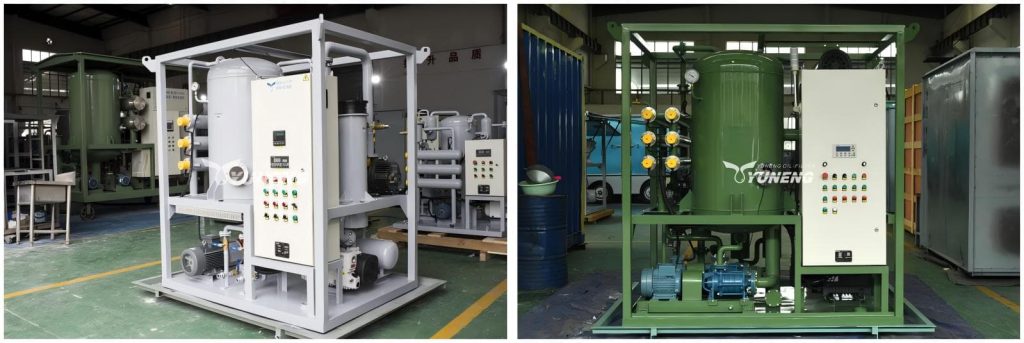
Once the required rated flow has been estimated, engineers can compare the result with available equipment configurations. YUNENG’s transformer oil purifier product range includes models rated at 1,800, 3,000, 6,000, and 9,000 LPH, alongside other capacities.
| Nominal rated capacity | Equivalent rated flow | Preliminary evaluation |
| 1,800 LPH | 1.8 m³/h | Evaluate for projects with lower required throughput |
| 3,000 LPH | 3.0 m³/h | Evaluate where the calculated requirement is within the verified operating capability |
| 6,000 LPH | 6.0 m³/h | A candidate for the illustrative 5,650 LPH requirement, subject to performance verification |
| 9,000 LPH | 9.0 m³/h | Evaluate when project throughput or schedule requirements justify the higher rated flow |
The numbers shown are nominal flow rates, not guaranteed actual processing rates and are not a universal recommendation for a particular size of transformer. The right selection process is to calculate the required capacity, find suitable rated models, and then check the full technical specification. Also, engineers need to confirm electrical requirements, heating capacity, hoover system configuration, filtration stages, operating limits and the required treatment results.
To compare two specific capacities directly, see YUNENG’s existing guide, Choosing Transformer Oil Purifier Capacity: 3000 LPH or 6000 LPH?. That article discusses model comparison: the method of calculation in this guide should be completed first, so that the comparison is based on actual project requirements. A higher LPH rating is not necessarily a better choice. The equipment must be compatible with the available power supply, site layout, treatment objective, maintenance window and budget.
Common Capacity Calculation Mistakes and Project Planning Checklist
Several calculation errors can lead to undersized equipment, unnecessary capital expenditure, or unrealistic maintenance schedules.
| Common mistake | Why it causes problems | Recommended approach |
| Selecting capacity from transformer MVA alone | MVA does not directly establish oil volume or processing time | Verify the actual oil inventory |
| Ignoring required processing turnovers | Underestimates cumulative throughput | Establish the treatment plan using oil condition and project requirements |
| Treating rated flow as guaranteed effective flow | May underestimate processing duration | Validate the expected operating flow |
| Counting setup time as processing time | Overstates available treatment hours | Calculate the effective operating window |
| Assuming all oil requires the same treatment | Different contamination and aging conditions require different approaches | Use initial oil test results to establish treatment objectives |
| Ignoring final quality verification | Can leave insufficient time for acceptance testing | Include sampling and verification in the schedule |
Before requesting a quotation, prepare the following information:
- Actual oil volume to be treated.
- Initial oil test results and required final oil quality.
- Planned processing turnovers or other defined treatment endpoint.
- Available maintenance window and expected interruption time.
- Site power supply and operating environment.
- Hose length, diameter, and elevation differences.
- Required equipment configuration and mobility.
- Applicable testing and acceptance requirements.
The information supplied allows the supplier to better determine the flow rate required and any limitations that a simple nominal LPH rating cannot provide. For projects involving moisture removal, degassing and filtration, the equipment specification should also specify how treatment performance will be verified. YUNENG’s guide to verifying transformer oil filtration and regeneration results provides a related reference for establishing pre-treatment baselines and evaluating post-treatment oil quality.
Frequently Asked Questions
Q1: Is transformer oil purifier capacity the same as actual filtration rate?
No. Rated capacity is the manufacturer’s nominal flow specification. Actual filtration rate depends on operating conditions, oil properties, piping resistance, filter condition, and equipment configuration.
Q2: Can transformer MVA rating determine the required oil purifier capacity?
No. Transformer MVA rating alone is insufficient. Capacity calculations should use the actual oil volume, treatment objective, planned processing turnovers, and available operating time.
Q3: How much additional capacity should be allowed for a transformer oil purification project?
There is no universal allowance for every project. Estimate the required rated flow using documented performance data, actual site conditions, and a justified effective-flow factor.
Q4: Does a higher LPH rating always reduce total purification time?
Not necessarily. Higher rated flow can reduce processing time if the equipment sustains that flow and achieves the required treatment result. Site constraints and oil condition may affect the actual duration.
Q5: How can I verify whether a transformer oil purifier meets my project requirements?
Compare the calculated rated flow with manufacturer performance data, operating limits, power requirements, and the required final oil quality. Confirm acceptance criteria and testing arrangements before procurement.
Conclusion: Calculate First, Select Equipment Second
A reliable transformer oil purifier capacity calculation begins with the actual oil volume and treatment objective, then converts the available processing time into a required effective flow rate. An appropriate allowance for real operating conditions will help engineers estimate the nominal capacity needed to complete the work within the project schedule.
The final selection should not be based on LPH rating alone. This should be supported by manufacturer performance data, site condition verification and clearly defined oil quality acceptance criteria. If you need project-specific evaluation, please visit the YUNENG transformer oil purifier product page and provide the oil volume, target treatment results, available operating window, and site conditions. These details provide a useful basis for the assessment of the required flow rate and equipment configuration.