Why SF6 Gas Recovery Systems Fail to Remove SO2: 4 Reasons

Power Utility Gas & Insulation Specialist
Table of Contents
As field engineers responsible for substation maintenance and transformer service, we frequently encounter complex technical anomalies that require immediate, methodical diagnostic action. During the maintenance of SF6-insulated switchgear (GIS) and related electrical apparatus, the SF6 gas handling process requires absolute precision. One critical, yet occasionally misdiagnosed, issue during field operations is the detection of persistent sulfur dioxide (SO2)contamination in SF6 gas that has already passed through a purification system.
When your gas analyzer triggers an alarm for SO2 after the gas has exited the filtration loop, it indicates a direct functional failure within the chemical purification stage of your equipment. This article provides a technical analysis of why this failure occurs, how to diagnose the system components, and the exact corrective actions required on-site.
Understanding the Dual-Stage Protection in an SF6 Gas Recovery System
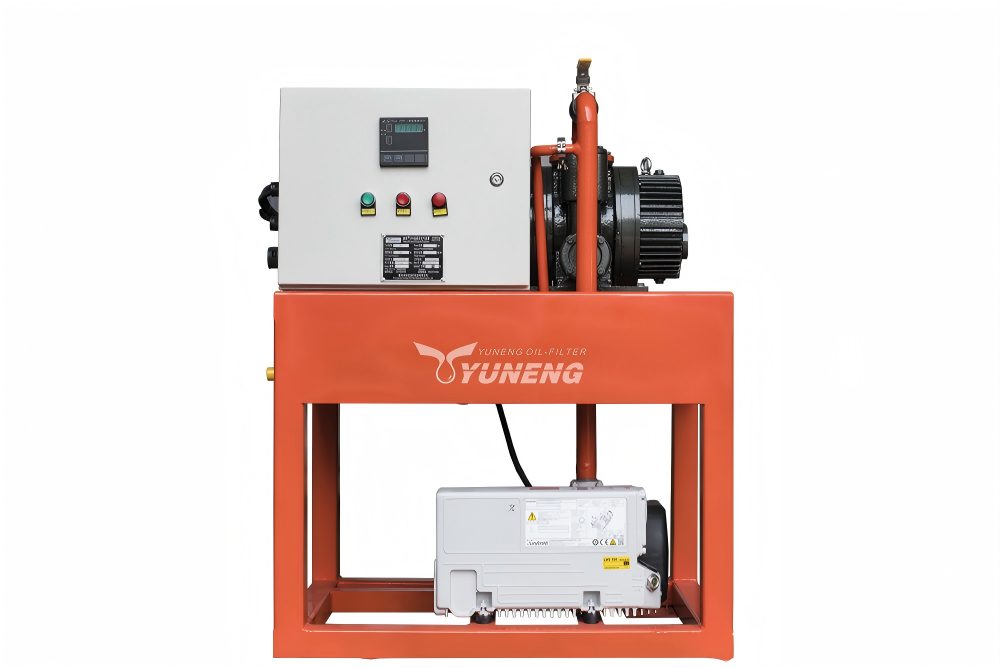
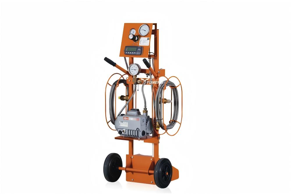
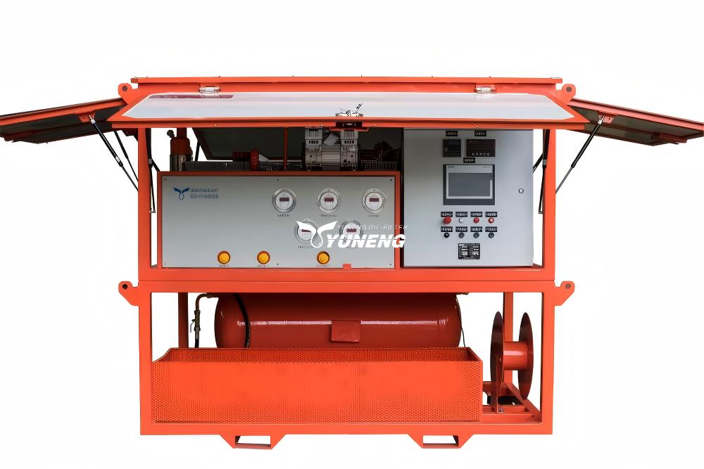
To accurately isolate the fault, we must analyze the internal configuration of a standard SF6 gas recovery system. The process of gas recovery does not employ a simple general filter system as would be employed for industrial equipment. Rather, the design of the SF6 gas recovery equipment involves two levels of separation, one for solids and another for chemicals.
Stage 1: The Mechanical Particulate Filter
When high-energy arcing or continued heating of SF6-insulated equipment occurs, the SF6 gas begins to degrade and reacts with the metal surfaces inside such equipment. As a result, solid and powdery waste is formed, for example, aluminum fluoride (AlF3) and copper fluoride (CuF2). The mechanical filtration system uses either porous membranes or sintered porous metal components to filter these microscopic particles out.
Technical Fact: Mechanical filters possess zero chemical affinity for gases. Gaseous contaminants like SO2 pass through the mechanical filter media without any reduction in concentration.
Stage 2: The Chemical Adsorption Bed (Deep Purification)
This stage is the primary defense against gas-phase degradation products. It consists of a pressure vessel containing synthetic desiccant and chemical adsorbents, typically a selective blend of zeolite molecular sieves (like 5A or 13X) and activated alumina. At this stage, moisture (H2O) and toxic, acidic gases such as SO2, thionyl fluoride (SOF2), and hydrogen fluoride (HF) are removed.
If your post-filtration testing shows measurable amounts of SO2, then the mechanical filtration stage is generally working properly, but the chemical adsorption bed has had a total operational failure.
Technical Causes of Adsorption Failure During SF6 Gas Recovery
Through systematic field data collection and root-cause analysis, we have classified the four primary reasons why an SF6 recovery process fails to eliminate SO2 gas.
Reason 1: Competitive Adsorption and Moisture Saturation
The synthetic molecular sieves used in an SF6 gas recovery system have a thermodynamic preference for polar molecules. It can be observed that the dipole moment of water is substantially greater than that of sulfur dioxide. As a result, there is a substantially higher binding affinity between the adsorption sites inside the crystalline lattice structure of a molecular sieve and moisture.
In case the SF6 gas drawn from the electric apparatus is highly humid, or if the pre-drying mechanism of the extraction machine breaks down, the molecular sieve will selectively absorb the water molecules. When the sites for adsorption are saturated with water, then two things happen:
- The material reaches its total adsorption capacity and can no longer capture SO2.
- A phenomenon known as “competitive displacement desorptivity” occurs. The incoming water molecules physically displace the SO2 molecules that were already trapped in the pores. This causes the filter to release a concentrated burst of SO2 back into the gas stream, increasing the post-filtration SO2 values beyond the initial inlet values.
Reason 2: Excessive Gas Flow Velocity (Insufficient Residence Time)
Chemical adsorption is a time-dependent mass transfer process. The gas molecules must diffuse from the bulk gas stream into the macropores and micropores of the adsorbent pellets, where they undergo physical or chemical binding.
In the case where the SF6 gas is drawn out using the field technician’s SF6 gas recovery equipment, running the unit at the highest possible rate will reduce the time taken in processing. However, the contact time of the gas flow inside the reactor will be too low because the gas will move fast enough inside the reactor. The gas carrying the SO2 molecules leaves the system without purifying the SO2 molecules.
Reason 3: Fluid Bypass via the “Tunneling Effect”
The physical packing arrangement of the adsorbent material inside the filter canister determines the uniformity of the gas flow distribution. If the adsorbent pellets are not tightly packed, or if mechanical vibration during equipment transport causes settling, internal voids and low-resistance pathways develop within the bed.
According to fluid dynamics, the gas stream will follow the path of least resistance. The SF6 gas channels rapidly through these open voids rather than dispersing evenly through the adsorbent matrix. This is known as the tunneling effect. When tunneling occurs, more than 80 percent of the adsorbent mass is bypassed, rendering the filter element ineffective despite containing unspent material.
Reason 4: Incorrect Adsorbent Media Selection
In some instances, generic or third-party maintenance kits utilize standard industrial desiccants, such as unmodified silica gel or standard blue indicating silica gel. While these materials are effective at removing moisture from air, they lack the specific pore diameter and surface chemistry required to bond with highly acidic SF6 decomposition gases. Standard silica gel cannot effectively capture SO2 molecules at typical field concentrations.
Standard Field Procedure for Rectification and Maintenance
When post-purification analysis detects SO2, field engineers must halt the SF6 gas recovery sequence immediately to prevent downstream cross-contamination of storage tanks. Implement the following four-step technical protocol:
| Step Number | Required Technical Action | Operational Objective |
| Step 1 | Suspend recovery operations and inspect the pre-drying or refrigeration unit. | To verify that the inlet gas temperature and moisture levels match the equipment specifications, preventing moisture overload of the primary filter. |
| Step 2 | Extract the spent filter core and replace the adsorbent media entirely. | To replace saturated media with a fresh mixture of grade 13X molecular sieves and chemically active, modified activated alumina. |
| Step 3 | Repack the filter vessel using mechanical compaction methods. | To eliminate all internal voids, settle the adsorbent material uniformly, and prevent the formation of fluid bypass channels. |
| Step 4 | Restart the system and adjust the recovery valve to 70% of maximum flow rate. | To reduce gas velocity, maximize the residence time within the adsorption bed, and allow complete chemical capture of SO2. |
Engineering Conclusion
In the field of high-voltage electrical engineering, chemical analytical data must guide all maintenance decisions. The presence of SO2 in processed gas is proof that the chemical purification parameters of your SF6 gas recovery system have been exceeded or compromised.
Unfiltered SO2 gas adds moisture to form sulfurous and sulfuric acid, which causes damage to internal compressor components, degrades internal seals, and reduces the dielectric purity of the reclaimed SF6 gas stock. If this happens, stop the process, find the moisture load, change the filter media using appropriate packing techniques, and control the gas velocity. These strict chemical and physical processing regulations are applied in order to ensure the longevity of the processing equipment and the high-voltage electrical assets.