How to Integrate a Dry Air Generator with a Transformer Vacuum Pump Unit
Table of Contents
Transformer drying often requires more than simply applying vacuum to the tank. During maintenance, installation, overhaul, or manufacturing, the transformer may need to alternate between vacuum evacuation and controlled air admission. If untreated atmospheric air enters the tank during this stage, it can introduce additional moisture and reduce the effectiveness of the drying process.
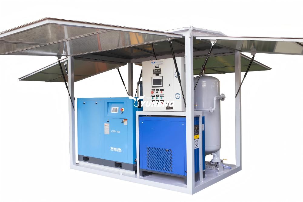
This is why a dry air generator and vacuum pump are often used as complementary transformer drying equipment. The vacuum pump controls the pressure environment by evacuating the transformer tank, while the dry air generator supplies low-moisture air when vacuum must be released, interrupted, or followed by dry-air circulation. Understanding how these two systems interact is essential when designing a reliable transformer vacuum drying system.
How Do a Dry Air Generator and Vacuum Pump Work Together?
A transformer vacuum pump unit removes air, water vapor, and other gases from the transformer tank and creates the required vacuum environment. A dry air generator supplies low-dew-point air for controlled backfilling, circulation, and moisture protection when the transformer is not maintained under vacuum.
In an integrated system, the equipment may be operated in a sequence such as:
Vacuum Evacuation → Dry-Air Backfilling → Heating or Circulation → Re-Vacuum → Final Drying Verification
The exact vacuum level, dry-air flow rate, dew point, temperature, and cycle duration should be determined according to the transformer design, insulation system, manufacturer’s requirements, and project-specific procedures.
Why Combine a Dry Air Generator with a Transformer Vacuum Pump?
The two machines solve different engineering problems. A vacuum pump reduces pressure inside the transformer tank and supports vacuum-assisted moisture removal. It is therefore the primary equipment for evacuation and vacuum treatment. A dry air generator provides air with controlled moisture content. Its main purpose is not to create vacuum, but to prevent humid atmospheric air from entering the transformer when vacuum needs to be released or when dry-air circulation is required.
A useful way to understand the difference is: The vacuum pump controls the pressure environment; the dry air generator controls the moisture content of the incoming air.
This distinction is important because a dry air generator is not normally a direct replacement for a vacuum pump, and a vacuum pump alone cannot provide a controlled supply of dry air.
When Should You Use Vacuum, Dry Air, or Both?
The correct configuration depends on the drying objective and operating stage.
| Operating Condition | Vacuum Pump | Dry Air Generator |
| Initial tank evacuation | ✓ | — |
| Vacuum-assisted drying | ✓ | — |
| Controlled vacuum release | — | ✓ |
| Dry-air backfilling | — | ✓ |
| Dry-air circulation | — | ✓ |
| Repeated drying cycles | ✓ | ✓ |
| Moisture protection during maintenance | — | ✓ |
1. Use the Vacuum Pump for Evacuation and Vacuum Drying
When the process requires the transformer tank to be evacuated or maintained under vacuum, the vacuum pump is essential equipment. Its performance affects evacuation time, vacuum recovery, and the ability of the system to maintain the required pressure condition.
2. Use the Dry Air Generator for Controlled Backfilling
When vacuum is released, untreated ambient air can bring moisture into the transformer. A dry air generator provides a controlled alternative by supplying air with a specified low dew point. This is especially useful during extended maintenance or when the transformer must be protected from humid ambient conditions.
3. Use Both for Repeated Drying Processes
For demanding applications, the two systems can be integrated into a repeated process:
Vacuum → Dry-Air Backfilling → Heating → Re-Vacuum → Dry-Air Circulation → Re-Vacuum
This approach gives engineers greater control over both pressure and moisture conditions throughout the operation.
How Does an Integrated Transformer Vacuum Drying System Work?
A typical configuration can be represented as:
Dry Air Generator → Dry-Air Pipeline → Transformer Tank ← Vacuum Pipeline ← Vacuum Pump Unit
The complete system may also include:
- Isolation valves
- Vacuum gauges
- Pressure gauges
- Dew-point monitoring
- Heating equipment
- Moisture-testing instruments
- Control systems
- Suitable vacuum and dry-air pipelines
For projects requiring a coordinated low-dew-point air supply and drying configuration, a transformer drying system can integrate dry-air generation, filtration, adsorption, and process control into a dedicated solution. The vacuum and dry-air circuits should be independently controlled so that operators can safely switch between evacuation and dry-air supply.
Step-by-Step Integration Process
1. Prepare the Transformer
Before connecting the transformer drying equipment, isolate the transformer and prepare it according to the applicable maintenance or manufacturing procedure. Inspect the tank, flanges, valves, pipelines, and connection points. Confirm that all components exposed to vacuum are suitable for the expected operating conditions.
Good preparation is important because leakage in the tank or connected piping can affect both vacuum performance and drying efficiency.
2. Connect the Transformer Vacuum Pump
The vacuum side normally consists of:
Transformer Tank → Vacuum Valve → Vacuum Pipeline → Vacuum Pump Unit
The pipeline should be properly sealed and appropriately sized for the required pumping performance. Vacuum gauges should be installed at suitable monitoring points so that the actual pressure condition of the transformer can be evaluated rather than relying only on the pump’s operating status.
3. Start Vacuum Evacuation
The vacuum pump gradually reduces pressure inside the transformer tank. During evacuation, operators should monitor:
- Vacuum pressure
- Pressure reduction
- Vacuum stability
- Pump condition
- Pipeline connections
- Potential leakage
If the required vacuum cannot be maintained, the first step should be to inspect the complete vacuum circuit rather than immediately assuming that the pump is undersized. Potential causes include tank leakage, valve leakage, flange sealing problems, or unsuitable pipeline connections.
4. Introduce Dry Air for Controlled Backfilling
When the process requires vacuum release, the dry-air circuit can be opened after the vacuum side is appropriately isolated. The typical flow path is:
Dry Air Generator → Regulating Valve → Dry-Air Pipeline → Transformer Tank
The supplied air should have a dew point suitable for the specific transformer drying or maintenance procedure. Air pressure and flow should also be controlled to avoid unnecessary pressure fluctuations.
5. Apply Heating and Dry-Air Circulation
Some transformer drying processes combine heating with vacuum and dry-air treatment. Heating helps release moisture from the transformer insulation, while vacuum evacuation removes the released water vapor and gases. Dry-air circulation can then help maintain a controlled low-moisture environment.
A possible process is:
Heating → Vacuum → Dry-Air Introduction → Circulation → Re-Vacuum
However, temperature and operating duration should always follow the transformer manufacturer’s process requirements. There is no universal temperature or cycle time that is suitable for every transformer.
6. Repeat Vacuum and Dry-Air Cycles
Moisture inside transformer insulation may not be removed uniformly during one cycle. Depending on the transformer condition and drying procedure, repeated cycles may therefore be required.
A typical sequence is:
Vacuum Evacuation → Moisture Removal → Dry-Air Backfilling → Moisture Release from Insulation → Re-Vacuum
The objective is to progressively reduce moisture while preventing unnecessary moisture re-entry when the transformer is exposed to air.
7. Verify the Final Drying Condition
Drying should not be considered complete simply because a target vacuum has been reached. Depending on the project, verification may include:
- Insulation moisture measurements
- Insulation resistance
- Oil moisture testing
- Dry-air dew point
- Vacuum holding performance
- Temperature records
- Other manufacturer-specified acceptance criteria
The final acceptance should be based on the applicable technical requirements rather than a single measurement.
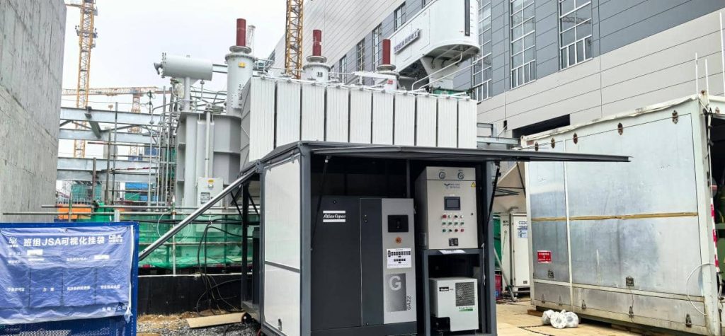
How to Connect a Dry Air Generator to a Transformer Vacuum Drying System
The dry-air and vacuum circuits should normally be arranged as separate controlled paths.
1. Dry-Air Side
The dry-air circuit supplies:
Dry Air Generator → Filter/Regulator → Isolation Valve → Transformer Tank
The system should minimize opportunities for humid ambient air to enter the pipeline.
2. Vacuum Side
The vacuum circuit consists of:
Transformer Tank → Isolation Valve → Vacuum Pipeline → Vacuum Pump Unit
The pipeline should be vacuum-tight and properly sized for the required pumping performance.
3. Control Side
A practical system should provide control over:
- Vacuum isolation
- Dry-air isolation
- Pressure
- Vacuum level
- Airflow
- Dew point
- Heating
- Process sequence
The key principle is that the vacuum and dry-air circuits should not form an uncontrolled common flow path.
How to Match a Dry Air Generator with a Transformer Vacuum Pump
A common misconception is that the dry air generator must have the same capacity as the vacuum pump.
It does not. The two systems are selected according to different operating requirements.
Vacuum Pump Capacity Depends Mainly On:
- Transformer tank volume
- Required evacuation time
- Target vacuum condition
- Vacuum pipeline configuration
- Leakage rate
- Required vacuum recovery time
Dry Air Generator Capacity Depends Mainly On:
- Transformer tank volume
- Required dry-air flow
- Backfilling time
- Circulation requirements
- Required dew point
- Continuous or intermittent operation
Therefore, equipment selection should be based on the complete drying process rather than a 1:1 capacity ratio.
What Parameters Should Be Considered?
| Parameter | Why It Matters |
| Transformer tank volume | Influences air replacement and evacuation requirements |
| Vacuum pumping speed | Affects evacuation and recovery time |
| Ultimate vacuum | Determines achievable vacuum conditions |
| Dry-air flow rate | Determines backfilling and circulation capability |
| Dew point | Indicates moisture level of supplied air |
| Pipeline diameter | Affects pressure drop and flow resistance |
| Drying cycle | Determines operating pattern |
| Operating environment | Influences equipment performance |
| Power supply | Determines site compatibility |
| Mobility | Important for field maintenance |
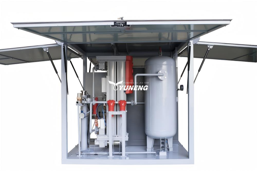
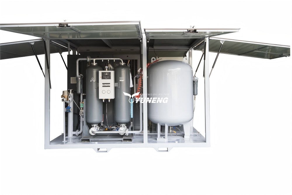
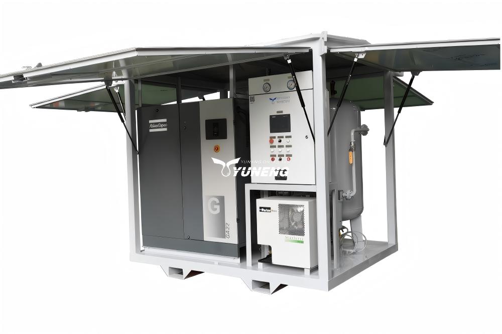
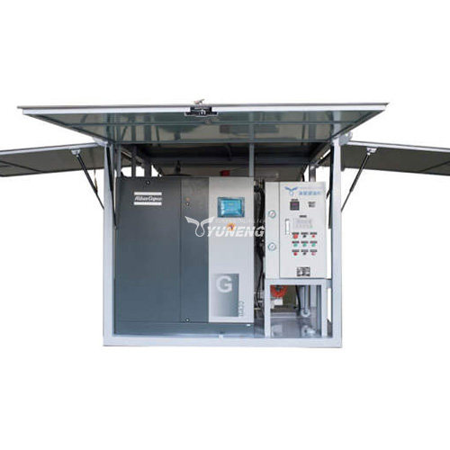
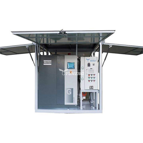
For example, YUNENG’s GF Series provides different dry-air capacity configurations, including mobile and higher-capacity models. The appropriate model should be selected according to the actual transformer volume, airflow requirement, dew point, operating cycle, and site conditions rather than transformer rated capacity alone.
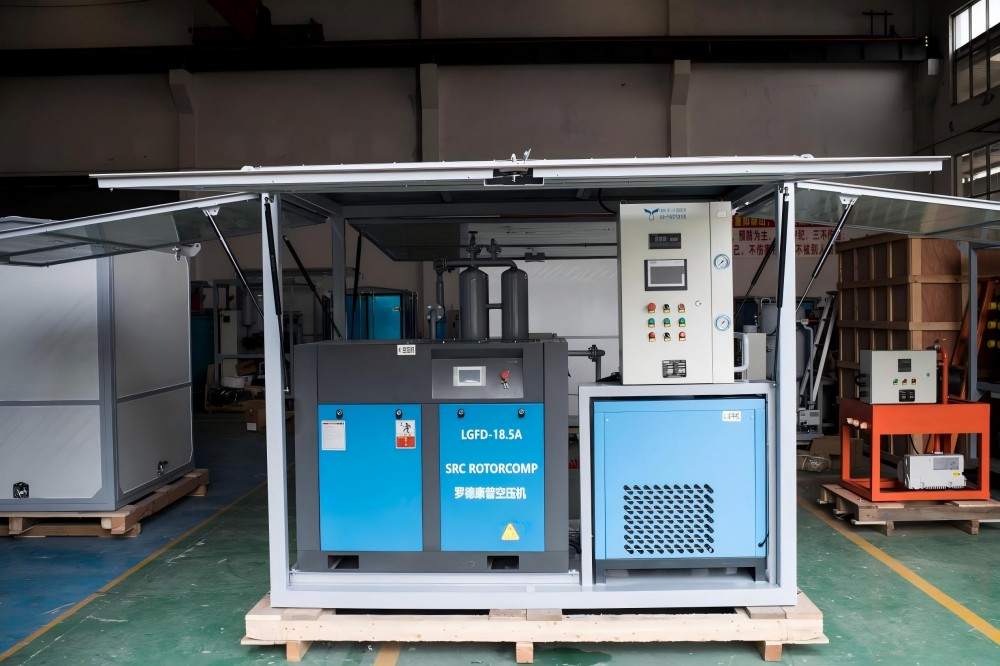
Does a Dry Air Generator Need the Same Capacity as the Vacuum Pump?
No. A vacuum pump and dry air generator have different performance objectives.
A vacuum pump is selected primarily for how quickly and effectively it can evacuate the transformer tank and maintain the required vacuum condition.
A dry air generator is selected based on how much low-moisture air is required for controlled backfilling and circulation.
For this reason, the correct question is not: “Should the two machines have the same capacity?” It is: “Can both machines provide the required performance throughout the complete drying cycle?”
This process-based approach produces a more reliable equipment configuration.
Can a Dry Air Generator Replace a Transformer Vacuum Pump?
In general, no. A dry air generator supplies conditioned air but does not perform the same function as a vacuum pump. If the process requires evacuation, vacuum-assisted drying, or removal of gases from the transformer tank, a suitable vacuum system is required.
Dry air is particularly useful when:
- Vacuum must be released
- The transformer requires controlled backfilling
- Moisture ingress must be minimized
- Dry-air circulation is part of the process
- The transformer must be protected during extended maintenance
The two systems should therefore be regarded as complementary transformer drying equipment.
Dry Air Vacuum Drying vs Vacuum-Only Drying
Vacuum-only drying can be appropriate when the transformer can remain under vacuum throughout the required process. However, some applications require controlled air admission or repeated operating cycles. In such cases, a combined system can provide better moisture control.
| Factor | Vacuum-Only | Vacuum + Dry Air |
| Vacuum evacuation | ✓ | ✓ |
| Vacuum-assisted drying | ✓ | ✓ |
| Controlled backfilling | Limited | ✓ |
| Low-moisture air supply | — | ✓ |
| Dry-air circulation | — | ✓ |
| Process flexibility | Moderate | High |
| Equipment complexity | Lower | Higher |
The combined configuration is particularly useful when the transformer drying procedure involves repeated vacuum cycles, controlled vacuum release, extended maintenance, or strict moisture-control requirements.
What Equipment Is Needed for a Complete Transformer Drying System?
A complete configuration may include:
| Equipment | Primary Function |
| Vacuum Pump Unit | Creates and maintains vacuum |
| Dry Air Generator | Supplies low-dew-point air |
| Heating System | Supports moisture migration |
| Vacuum Gauge | Monitors vacuum |
| Dew Point Meter | Monitors dry-air quality |
| Isolation Valves | Controls the two flow circuits |
| Control System | Coordinates equipment operation |
| Moisture Testing Equipment | Verifies drying results |
The final configuration should be determined according to the transformer type, project procedure, required capacity, and site conditions.
Common Integration Problems and Troubleshooting
1. Vacuum Cannot Be Maintained
Check the system in sequence:
Transformer Tank → Flanges → Valves → Vacuum Pipeline → Vacuum Pump
Tank or pipeline leakage should be ruled out before changing the pump capacity.
2. Dry-Air Dew Point Is Too High
Possible causes include:
- Saturated adsorption material
- Insufficient regeneration
- Excessive inlet-air moisture
- Excessive airflow demand
- Pipeline leakage
- Sensor problems
The dry-air generator should be evaluated as a complete system rather than judging performance from one operating parameter.
3. Moisture Increases After Vacuum Release
If moisture rises after vacuum is released, check whether untreated atmospheric air is entering the transformer and whether the dry-air system is supplying air with the required dew point.
4. Drying Takes Too Long
Long drying times can result from:
Insufficient vacuum performance + inadequate heating + high moisture content + poor dry-air quality + leakage + moisture migration from insulation
Troubleshooting should therefore consider the complete process rather than focusing only on the vacuum pump or dry air generator.
Real-World Application of Integrated Transformer Drying Equipment
Large transformer maintenance projects may require several pieces of equipment to work together rather than relying on a single machine.
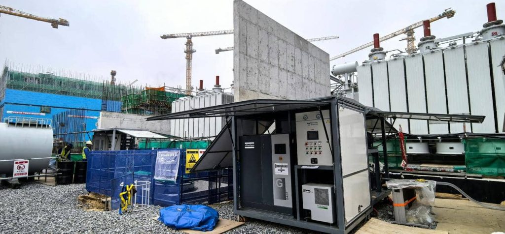
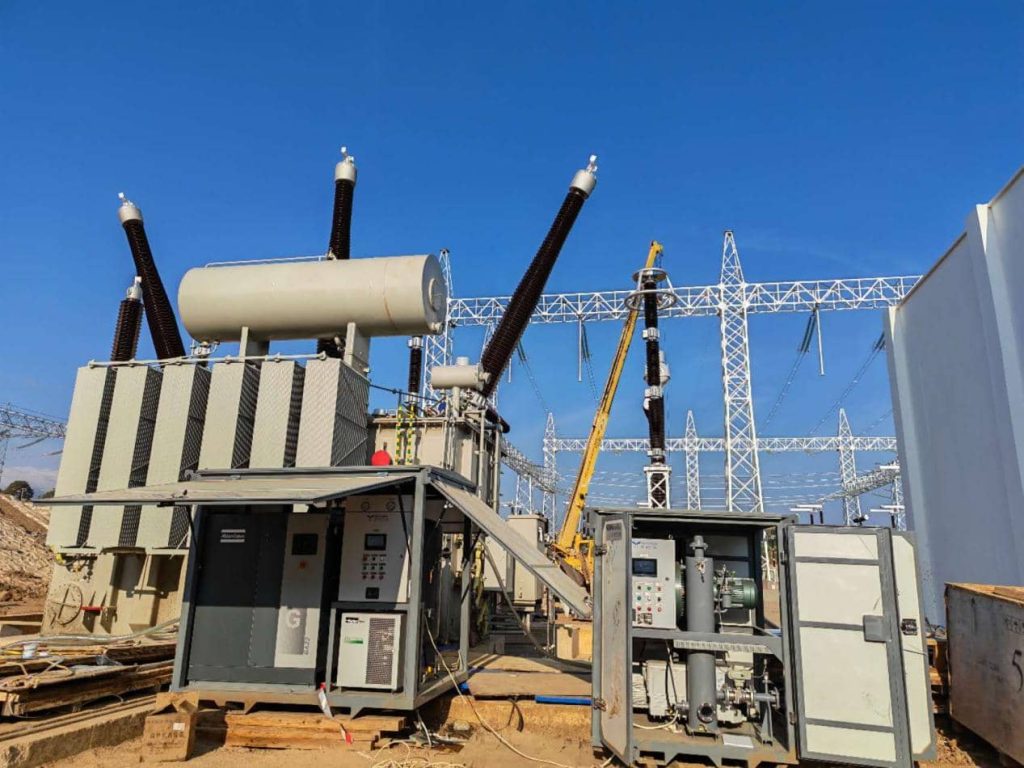
YUNENG’s project portfolio includes dry air generator applications, including a 420 m³/h dry air generator, as well as field projects involving transformer dry-air generators, vacuum pumping units, and transformer oil purification equipment. Such configurations demonstrate how dry-air equipment can be integrated into broader transformer maintenance workflows.
For a specific project, the equipment combination can be determined according to transformer volume, required vacuum performance, dry-air capacity, dew point, power supply, mobility requirements, and operating conditions.
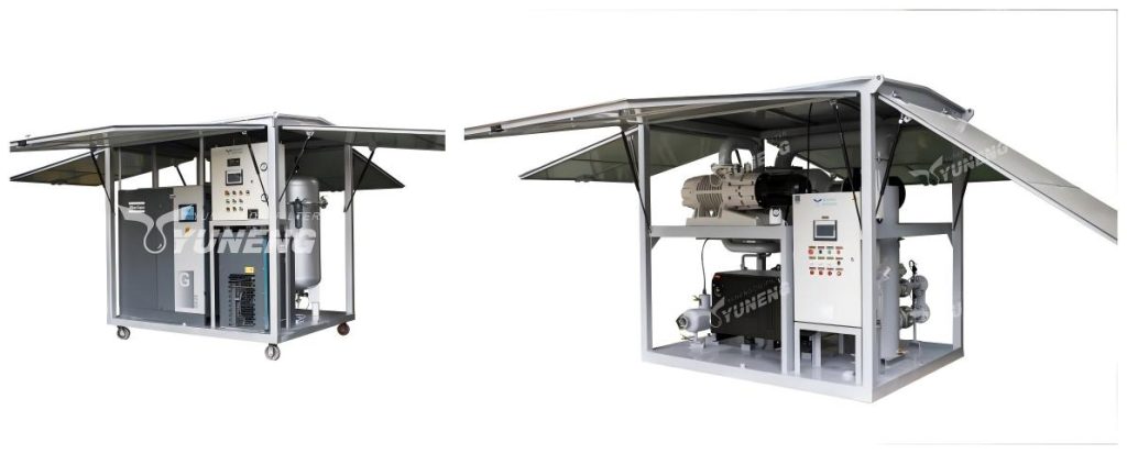
How to Select the Right Transformer Drying Equipment
Different users may have different priorities.
1. Transformer Manufacturers
Manufacturers generally require repeatable processes, stable equipment performance, suitable capacity, and integration with production drying systems.
2. Power Utilities
Utilities may prioritize reliable field operation, mobility, quick deployment, and compatibility with transformers of different sizes.
3. Transformer Service Contractors
Service contractors may need mobile equipment that can be transported between sites and rapidly connected to different transformer configurations.
For these applications, a combined system may include a transformer vacuum pump, dry air generator, heating system, monitoring instruments, and associated valves and pipelines. YUNENG can configure transformer drying equipment according to project requirements, including dry-air capacity, dew point, vacuum performance, electrical supply, control configuration, and mobility.
FAQs
Q1: Can a dry air generator replace a transformer vacuum pump?
No. A dry air generator supplies low-moisture air, while a vacuum pump creates the vacuum required for evacuation and vacuum-assisted drying. They perform different functions and may be used together in a complete transformer drying process.
Q2: Can a vacuum pump and dry air generator operate at the same time?
They normally operate in coordinated stages rather than being connected as an uncontrolled common flow path. Isolation valves and a suitable control arrangement should be used to separate the vacuum and dry-air circuits.
Q3: Does a dry air generator need the same capacity as a vacuum pump?
No. Their capacities are determined by different parameters. Vacuum pump selection depends mainly on evacuation requirements, while dry-air generator selection depends on airflow, backfilling, circulation, dew point, and the transformer drying procedure.
Q4: Why is dry air used when breaking transformer vacuum?
Dry air prevents untreated humid atmospheric air from entering the transformer. Low-dew-point air helps maintain a controlled moisture environment when vacuum must be released.
Q5: How do you select a dry air generator for a large transformer?
Consider transformer tank volume, required dry-air flow, dew point, backfilling time, circulation requirements, operating cycle, site conditions, and power supply. Transformer rated capacity alone is not sufficient for equipment selection.