How to Perform On-Load Transformer Oil Regeneration

Oil Purification & Vacuum Technology Expert
Table of Contents
As field maintenance engineers, we face a constant challenge: keeping high-voltage assets running efficiently without causing unplanned downtime. Today, I want to talk about a highly effective method for achieving this: performing on-load transformer oil regeneration using a mobile transformer oil regeneration plant. This technical guide focuses specifically on live, energized processing. It covers how the technology functions, the critical safety metrics we must monitor on-site, and the practical limitations that dictate when we cannot perform this procedure.
The Reality of Transformer Oil Degradation in the Field
In our daily substation operations, we monitor transformers operating under constant thermal and electrical stress. In the long years of continuous service, the hydrocarbon molecules in the transformer insulation oil break down by oxidation. This chemical degradation leads to the formation of some sub-products: peroxides, soluble acids, low-molecular-weight polar compounds, and finally insoluble sludge.
Standard physical filtration—such as using a basic particulate filter or a standard vacuum dehydrator—only addresses free water and solid particles. It cannot remove the chemically dissolved acids or the sludge precursors. If you only perform standard mechanical filtration, these acidic compounds remain in the oil, continuing to degrade the cellulose paper insulation and speeding up the aging of the transformer’s core components.
To actually fix this issue, you must physically remove these polar degradation products from the oil matrix. Before, this meant shutting down the system, draining the unit, and refilling it with new oil. But this is not without its considerable logistical challenges, high replacement costs, and unwelcome downtime. Hence, the treatment of oil by the use of a dedicated transformer oil regeneration plant while the transformer is in service is now an accepted industry practice.
Technical Process of an On-Load Transformer Oil Regeneration Plant
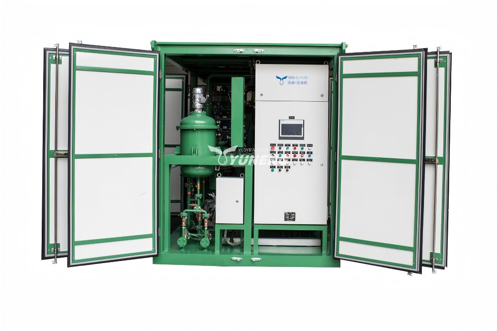
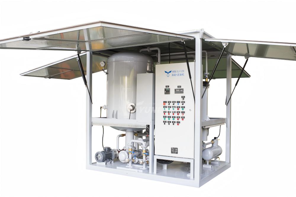
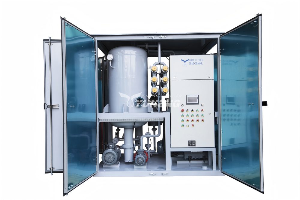
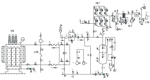
When we set up a mobile transformer oil regeneration plant next to an energized transformer, we establish a secure, closed-loop fluid circuit. The oil moves through a specific multi-stage physical and chemical treatment process before returning to the transformer tank.
Step 1: Oil Extraction and Temperature Regulation
The intake pump of the regeneration unit draws the aged oil from the bottom drain valve of the transformer. The oil passes through an inline pre-heater that raises the oil temperature to a desired operating range, normally 50 °C to 60 °C. This temperature window is necessary as it reduces the viscosity of the oil, which optimises the fluid dynamics for the chemical absorption stage.
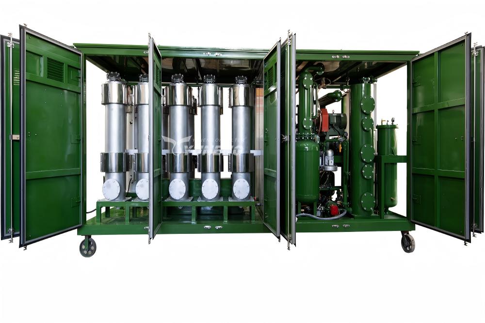
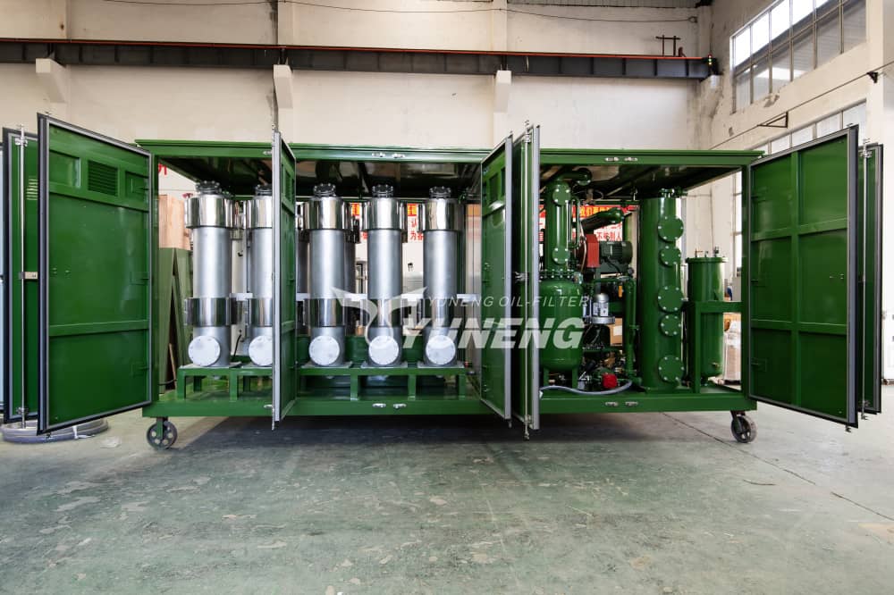
Step 2: Adsorption and De-Coloration
The heated oil is pumped under controlled pressure into a series of columns packed with a highly porous adsorbent media, most commonly Fuller’s Earth (attapulgite clay) or specially engineered activated alumina. And that’s the essence of transformer oil regeneration process. The porous clay is a chemical filter. It holds polar molecules (including dissolved acids, ketones, aldehydes, and byproducts of decaying sludge) within its structure, whilst allowing the non-polar hydrocarbon oil molecules to pass through unimpeded. This stage returns the oil to its original clear light-yellow colour from the dark, degraded amber it had become.
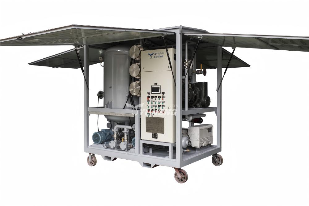
Step 3: Vacuum Degassing and Dehydration
After passing through the clay columns, the oil enters a multi-stage vacuum flash distillation chamber. This chamber operates under a high vacuum (typically below 5 mbar) and a temperature of roughly 60°C. The combination of high vacuum and thin-film oil distribution causes dissolved moisture and low-weight combustible gases to rapidly boil off. This reduces the micro-water content to under 10 ppm, directly recovering the oil’s dielectric breakdown voltage.
Step 4: Antioxidant Inhibitor Re-injection
Because the adsorbent clay columns remove not only the bad acids but also the oil’s natural oxidation inhibitors, the oil leaves the treatment columns completely uninhibited. To prevent rapid re-oxidation, the transformer oil regeneration plant uses an automated dosing system to inject a precise amount of synthetic antioxidant—typically 2,6-di-tert-butyl-paracresol (DBPC/T501)—back into the oil stream, bringing the concentration back up to the standard 0.3% by weight.
Step 5: Safe Return to the Transformer
The fully processed, dried, and inhibited oil passes through a final 1-micron particulate check filter before being pumped back into the top valve of the transformer conservatory tank.
The “Online Wash Effect” and Engineering Advantages
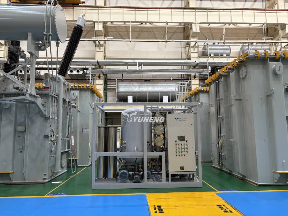
From a field engineering perspective, running the transformer oil regeneration process online (while the transformer is energized and under load) provides significant technical advantages over traditional offline processing.
The Dynamic “Online Wash Effect”
- The Offline Problem (Cold Precipitation): When a transformer is offline and cold, internal sludge thickens, precipitates out of the fluid, and physically adheres to the solid winding insulation, horizontal radiational ducts, and internal tank walls. Offline filtration or oil changes leave this stuck sludge behind. Once the transformer is re-energized and heats up, the old sludge dissolves back into the fresh oil, causing rapid re-contamination.
- The Online Solution (Thermal Solubility): The core oil temperature is naturally high (usually 60 ℃ to 80 ℃) with on-load regeneration. At these temperatures, the sludge is completely dissolved in the oil matrix, so that it can be drawn directly into the transformer oil regeneration plant.
- Continuous Chemical Dissolution: As the plant continuously extracts the hot, contaminated oil, traps the polar impurities in its clay filters, and returns clean, unsaturated oil to the tank, the processed oil acts as an active solvent. It strips away and “washes” remaining sludge deposits off the internal paper insulation and cooling ducts, simultaneously cleaning both the fluid and the internal physical structure.
Deep Solid Insulation Dehydration
- Moisture Equilibrium Imbalance: The returned oil is exceptionally dry (under 10 ppm), which creates a stark moisture gradient between the wet cellulose paper winding insulation and the dry fluid.
- Non-Destructive Dry-Out: Over an extended cycling period, this equilibrium imbalance continuously drives trapped water out of the paper insulation and into the oil stream, where it is permanently removed by the regeneration plant’s vacuum system. This achieves a deep, active dry-out of the solid insulation system without taking the asset offline.
On-Site Safety Controls and Operational Boundaries
Performing maintenance on a live, high-voltage transformer requires strict adherence to safety controls. As field engineers, we must monitor specific operational parameters on the transformer oil regeneration plant to eliminate risks to the live asset.
| Parameter | Operational Risk | Field Mitigation Target |
| Oil Flow Velocity | High velocity causes flow-induced electrostatic charging (static electrification), which can lead to catastrophic internal tracking or dielectric discharge. | Keep flow rates strictly below the manufacturer’s recommended limits (typically under 4,000 liters/hour depending on pipe diameters). |
| Air Entrainment | Micro-air bubbles introduced via leaky pump seals or hoses can travel into the high-voltage winding zone, causing immediate partial discharge (PD) or full phase-to-ground flashover. | Utilize dual-stage automatic air-venting systems and inline optical bubble detectors linked to automatic shutdown valves. |
| Oil Level Fluctuations | Sudden changes in oil volume can trip the Buchholz relay or uncover live windings. | Use automated PLC-controlled interlocking valves that match inlet and outlet flow volumes down to the milliliter. |
Absolute Contraindications (When NOT to perform online regeneration)
Before connecting a transformer oil regeneration plant to any live asset, you must first perform a comprehensive Dissolved Gas Analysis (DGA). You must immediately cancel the online procedure if the lab report shows any of the following warning signs:
- Active High-Energy Faults: The presence of acetylene (C2H2) above acceptable standard limits, or a steep upward trend in hydrogen (H2) and ethylene (C2H4). These indicate an active internal arc or severe localized thermal fault. Pumping oil through an active fault zone can destabilize the gas bubble equilibrium and cause a major failure.
- Extreme Advanced Oil Carbonization: If the oil color is completely black, heavily loaded with free carbon particles, and shows an acid number exceeding 0.6 mg KOH/g, the fluid is too unstable for online cycling. The fluid circulation could stir up heavy conductive sediments from the bottom of the tank, causing an immediate internal flashover. These extreme cases require a complete offline oil flush and replacement.
Summary for Engineering Decision Making
Using an online transformer oil regeneration plant is an efficient, technically sound way to manage substation assets. It allows us to fully restore the acidity, interfacial tension, color, and dielectric breakdown strength of the oil without interrupting power delivery to the grid.
The online process cleans the internal winding structures far better than cold, offline methods by using the oil’s natural thermal solubility to remove sludge. However, as field engineers, we must always perform a preliminary DGA screening before starting the work. We must also closely monitor our flow velocities and air-elimination systems throughout the entire run to ensure the procedure is completed safely.