How Transformer Oil Purification Improves Insulating Oil BDV

Oil Purification & Vacuum Technology Expert
Table of Contents
In high-voltage electrical engineering, ensuring the dielectric strength of insulating oil is a primary maintenance objective. As a field maintenance engineer, I regularly evaluate the transformer oil BDV to determine the operational safety of power transformers. A sudden drop in BDV values often indicates complex contamination involving dissolved water, particulate matter, and combustible gases. Simply running fluid through a generic loop multiple times without precise process control rarely achieves the strict commissioning or operational standards required today. To effectively restore insulating properties, field operators must optimize the processing parameters of their fluid conditioning equipment and understand the physical interactions occurring within the dielectric medium.
Tuning Your Transformer Oil Filtration System for Peak Performance
When addressing low breakdown voltage, the initial step involves adjusting the operational parameters of your transformer oil filtration system. A common operational error is assuming that high flow rates lead to faster results. In the field, achieving a high BDV requires sufficient dwell time within the vacuum chamber to allow complete degasification and dehydration.
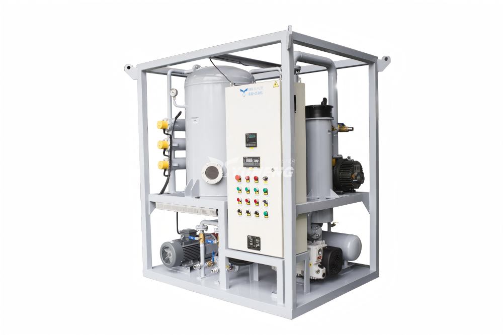
1. The Vacuum Paradox and Two-Stage System Mechanics
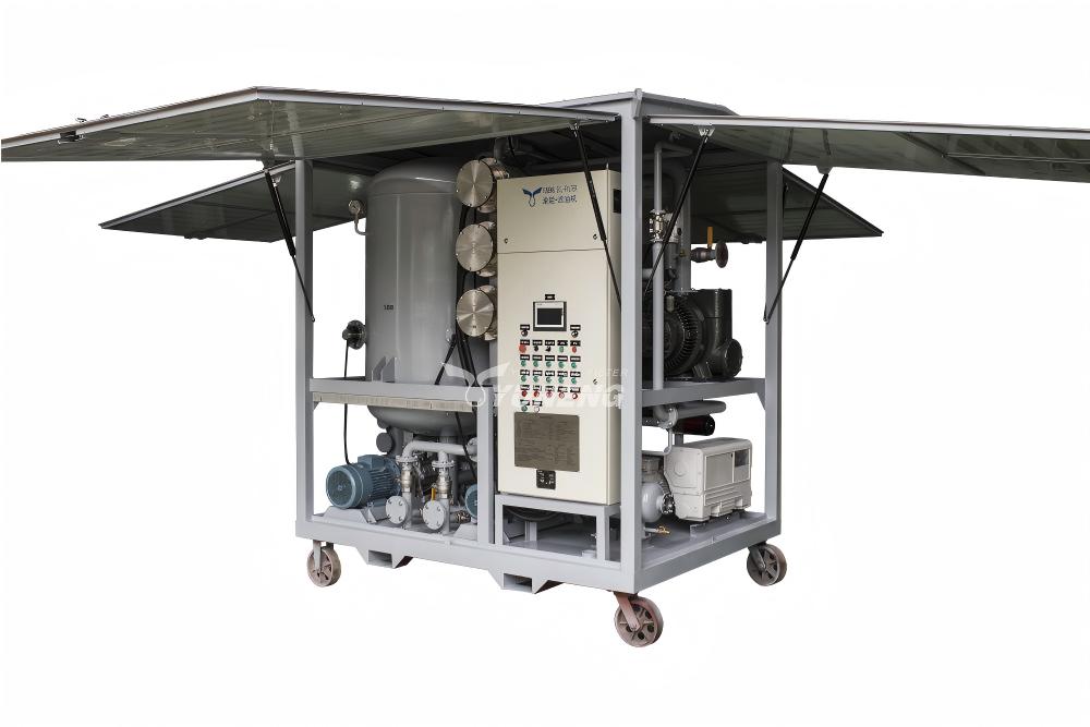
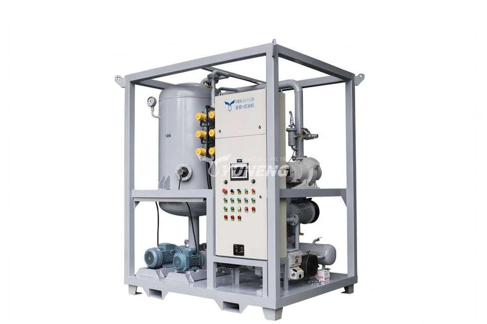
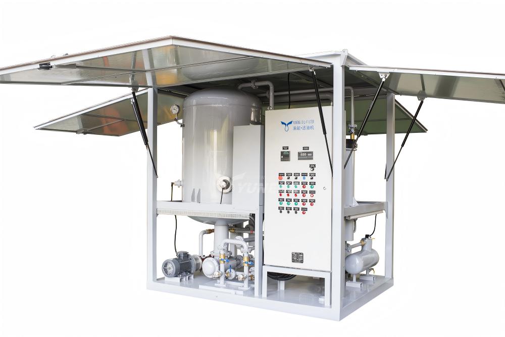
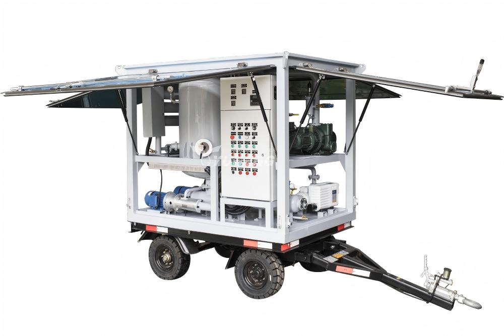
Standard single-stage vacuum chambers often lack the negative pressure required to extract tightly bound dissolved water molecules from aged or highly viscous insulating oil. For high-voltage and extra-high-voltage (EHV) applications, a two-stage transformer oil filtration system utilizing both a rotary vane vacuum pump and a Roots booster pump is necessary.
The main vacuum level should be strictly maintained at or below 133 Pa (target limit down to 10 Pa for no-load conditions). 500 Pa. should be maintained for the backing vacuum stage. This high negative pressure differential reduces the boiling point of the dissolved water, so the moisture flashes into vapor without thermal degradation of the oil hydrocarbons.
2. Establishing the Thermal Sweet Spot
To facilitate efficient moisture extraction, the oil must be heated to lower its surface tension and kinematic viscosity. However, temperature management requires strict operational boundaries:
- Underheating (<45°C): The kinetic energy of the water molecules remains insufficient to break their molecular bonds with the oil, resulting in poor dehydration efficiency regardless of the vacuum depth.
- Overheating (>65°C): Excessive thermal stress risks triggering localized thermal cracking of the mineral oil molecules, generating dissolved fault gases and accelerating long-term oxidation.
Therefore, field operations for mineral insulating oil should be strictly maintained within the optimal temperature range of 45°C to 65°C. Within this specific thermal window, the oil achieves ideal fluidity, maximizing the surface area of the oil film as it passes through the three-dimensional atomizing elements inside the vacuum separation tower.
Micro-Particle Elimination: Preventing the “Bridging Effect”
Field data often reveal situations where the moisture content of an oil sample is low (e.g., <10 ppm), but the breakdown voltage is nevertheless below acceptable limits. This technical anomaly is generally caused by microscopic particulate contamination and is a major factor in the mechanics of transformer oil purification.
In an active electrical field, suspended particles such as carbon soot, metallic shavings, and cellulose fibers polarize. These polarized impurities align themselves along the lines of the electric field force between the electrodes, creating a conductive physical pathway known as the “bridging effect.” When the voltage increases, electrical discharge occurs along this particle bridge at a much lower threshold than it would in clean oil.
To eliminate this phenomenon during transformer oil purification, the filtration sequence must utilize multi-stage particulate filters with precise nominal and absolute ratings. While a 10 μm coarse filter is sufficient for protecting the internal pumps of the machine, the final polishing stage must utilize a high-efficiency media rated at 1 μm to 3 μm.
Engineers must monitor the differential pressure gauges across these filter housings; a differential pressure exceeding 0.2 MPa indicates filter saturation, which can cause the bypass valve to crack open or force finer particulates through the media, resulting in secondary contamination of the processed oil.
Dealing with Degraded Oil: When Simple Purifying Isn’t Enough
Standard physical degassing and mechanical filtration are not sufficient to restore the dielectric properties of legacy transformers or units exposed to long thermal overloads. As insulating oil ages, it undergoes oxidation, leading to the formation of chemical byproducts such as polar compounds, organic acids, and sludge. These dissolved aging products directly increase the dielectric loss factor (tanδ) and provide free ions that significantly lower the BDV.
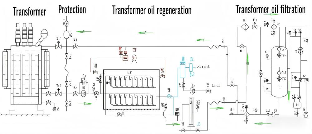
A mechanical transformer oil purifier utilizing only heat and vacuum cannot remove these dissolved chemical contaminants because they do not vaporize and cannot be trapped by mechanical particulate media. In these scenarios, the processing setup must incorporate a comprehensive transformer oil regeneration system.
| Property | Standard Vacuum Purifier | Regeneration System (Full Clay/Adsorbent) |
| Water Removal | Excellent (Free and Dissolved) | Excellent |
| Gas Removal | Excellent | Excellent |
| Particulate Removal | Depends on filter micron rating (1−5 μm) | Excellent |
| Acid/Polar Compound Removal | None | Complete (Via chemical adsorption) |
| Sludge Dissolution | None | High capability |
| Color Restoration | Minimal improvement | Complete restoration to clear/light yellow |
The transformer oil regeneration process routes the heated oil through specialized reactive columns containing fuller’s earth, activated alumina, or porous synthetic sorbents. These media beds rely on molecular adsorption to extract acids, sludge precursors, and polar decay products from the fluid. Integrating chemical regeneration with a vacuum transformer oil purifier neutralizes the total acid number (TAN) to <0.03 mg KOH/g and reduces the dielectric loss, establishing a stable chemical foundation that allows the BDV to exceed 65 kV consistently.
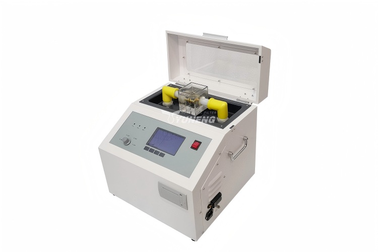
Avoiding the “Fake Low”: Standardizing BDV Testing Protocol
A significant percentage of low BDV readings recorded in field logs do not accurately reflect the condition of the fluid inside the transformer tank; instead, they represent operational errors during the analytical phase. To get accurate data, testing protocols with a transformer oil BDV tester must be rigorously standardized.
1. Eliminating Entrained Air Microbubbles
When oil is transferred from a sampling container into the test cell of a transformer oil BDV tester, air becomes entrained in the fluid, creating microscopic bubbles. Air has a much lower dielectric constant than insulating oil. If the test sequence begins immediately, these bubbles migrate into the gap between the spherical or VDE electrodes, ionizing under low electrical stress and causing a premature breakdown. This protocol necessitates that the oil sample remain still in the test cup for at least 15 minutes prior to testing with electricity. This is because any bubbles within the oil need time to rise to the surface and escape.
2. Environmental Controls and Sample Integrity
The physical properties of clean, processed transformer oil make it highly hygroscopic. If field testing is conducted in ambient conditions where the relative humidity exceeds 70%, the oil surface exposed to the air rapidly absorbs moisture. This localized moisture increase in the test cup alters the breakdown characteristics, rendering the test invalid.
Furthermore, operators must never clean the internal surfaces of the test cell with cellulose-based materials or cloth towels, as these introduce microfibers into the gap. The test cup and electrodes should only be cleaned using a portion of the actual oil sample slated for analysis.
Conclusion & Engineer’s Field Checklist
Maximizing the breakdown voltage of transformer insulation fluid is an engineering objective achieved by managing measurable physical and chemical properties. Field engineers can control the dielectric reliability of their infrastructure by maintaining high vacuum thresholds, controlling process temperatures, sub-micron particulate filtration, and degraded oil with adsorbent media.
To ensure consistent execution during maintenance turnarounds, utilize the following operational parameter checklist before verifying oil quality with the diagnostic instrumentation:
- System Vacuum Pressure: ≤133 Pa (Main Chamber) | ≤500 Pa (Backing Stage)
- Oil Processing Temperature: 45℃~65 ℃
- Final Stage Filter Rating: 1 μm absolute beta-rated element
- Adsorbent Media Check: Deploy regeneration modules if TAN exceeds 0.1 mg KOH/g
- Pre-Test Settling Window: ≥15 minutes inside the testing cell
- Maximum Permissible Testing Humidity: <70% Relative Humidity